High-Speed Connectors & Signal Integrity
High-Speed Connectors & Signal Integrity
Articles
25 entries
What Does "OCP/ORV3 Compliant" Mean? Connector Requirements Checklist
OCP connectors get called "compliant" loosely — but there's informal spec conformance, and then there's OCP Accepted™ and OCP Inspired™, two very different formal designations. Here's the actual checklist.

Blind-Mate RF Coaxial Connectors: Push-On vs. Threaded Interfaces in Rack Systems
Slide-in modular RF chassis demand true blind-mate capability. Compare push-on interfaces like SMP/SMPM with traditional threaded designs across alignment and signal loss.
Single Pair Ethernet Connectors: M8 vs. M12 vs. Automotive-Specific Variants
Single Pair Ethernet reduces weight and complexity by delivering data and power over one pair. Explore physical differences between industrial M8/M12 and automotive SPE variants.

PCIe Add-In Card Bracket & Form Factor Guide (Full-Height vs Low-Profile)
A definitive guide to PCIe add-in card mechanical form factors. Learn dimensions, retention mechanisms, and thermal chassis rules for full-height and low-profile cards.

PCIe CEM Slot Keying Explained: x1, x4, x8, x16
Demystify PCIe card edge notches and slot keying. Learn why physical slot length does not always equal electrical lanes and how open-ended slots enable flexible expansion.

PCIe Gen7 Connector & Signal Integrity Explained
PCIe Gen7 doubles data rates to 128 GT/s using PAM4 encoding. Learn how this massive leap impacts connector mechanics, insertion loss budgets, and PCB signal integrity.

PCIe Power Delivery: Slot Power Limits and Add-In Card Power Connectors
A complete technical breakdown of PCIe power delivery. Explore the 75W slot rail limit, auxiliary cable configurations, and design rules for high-power cards.
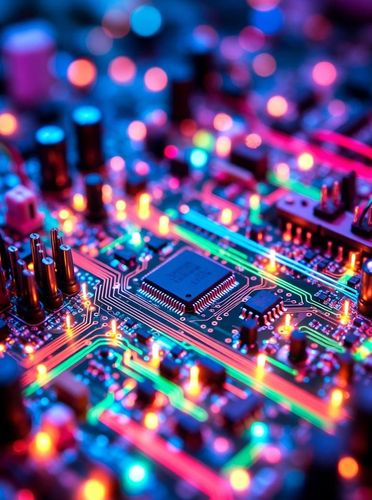
PCIe Gen7 Connector Design: What Changes at 128 GT/s
PCIe Gen7 pushes interconnect design to 128 GT/s using PAM4. Explore signal integrity margins, insertion loss budgets, and physical CEM slot expectations.

CEM Slot Explained: PCIe Card Electromechanical Connector Guide
The PCIe Card Electromechanical (CEM) slot is the industry-standard card-edge connector defined by PCI-SIG. This guide covers CEM anatomy, lane scaling, signal integrity parameters, and Gen 5 through Gen 7 design changes.

What Is Signal Integrity? A Beginner's Guide for Hardware Engineers
Signal integrity (SI) measures the physical quality of an electrical signal as it travels from transmitter to receiver. This guide covers reflections, crosstalk, attenuation, ground bounce, eye diagrams, and when SI starts to matter.

Differential Signals & Intra-Pair Skew: Why Distance Matches Matter
In gigahertz digital links, if one wire in a differential pair is even half a millimeter longer than its partner, your high-speed signal arrives out of phase, turning clean data into unreadable noise.

Demystifying Cable Impedance: Why 50, 75, and 100 Ohms Matter
Cable impedance isn't something you can measure with a standard multimeter—it's an AC property determined purely by physical geometry and insulation distance.

Skin Effect & AC Loss: Why High-Frequency Signals Hug the Surface
As signal frequencies rise into the megahertz and gigahertz range, electricity refuses to flow through the center of a copper wire, crowding onto the outer skin instead.

Why Ethernet Wires Are Twisted: Understanding Crosstalk & Lay Length
Unwrapping a multi-pair raw cable reveals that every pair is twisted at a slightly different tightness—a simple geometric design that prevents signals from bleeding into adjacent lines.
How to select connectors for high-speed data transmission
Master the step-by-step selection framework for high-speed interconnects. Evaluate S-parameters, pin density, mechanical reliability, and breakout footprint layout rules.
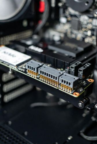
Why connector design becomes harder at 56Gbps and 112Gbps
Explore the physical challenges of ultra-high-speed signal routing at 56G and 112G SerDes rates. Learn how PAM4 modulation, skin effect, dielectric loss, and micro-reflections impact connector design.
Differential pair routing guidelines for high-speed connectors
Master high-speed differential pair PCB layout techniques around connector breakout zones. Learn length matching, phase skew control, via placement, and reference plane continuity.

Crosstalk in connectors: Causes and solutions
Examine the physical causes of capacitive and inductive crosstalk in high-speed connectors. Learn how NEXT, FEXT, and ground-pin shielding mitigate inter-channel noise.

What is signal integrity? A beginner's guide
Understand the core concepts of signal integrity (SI) in hardware engineering. Learn how attenuation, reflections, jitter, and crosstalk affect high-speed digital signals.
What is differential signaling? LVDS, PCIe, USB explained
Learn how differential signaling eliminates common-mode noise and ground bounce. Explore low-voltage differential protocols including LVDS, PCIe, and USB in high-speed hardware.
Insertion loss vs return loss explained
Master S-parameters for high-speed connectors. Understand the physical difference between insertion loss (S21) and return loss (S11), and how to interpret frequency response plots.

Impedance matching in high-speed connectors explained
Learn how impedance matching prevents signal reflections in high-speed connectors. Master characteristic impedance tuning, parasitic compensation, and footprint layout optimization.
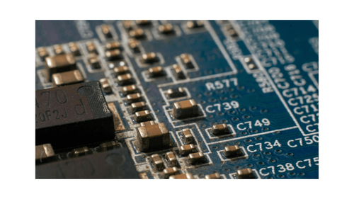
Signal integrity problems in high-speed connectors
Examine the root causes of signal degradation in high-speed connectors. Learn how impedance discontinuities, mode conversion, and skew impact high-bandwidth PCB interfaces.

High-speed connectors explained: What engineers need to know
Discover how high-speed connectors maintain signal integrity at gigabit data rates. Learn about impedance control, shielding mechanisms, and pin layout strategies for high-frequency designs.
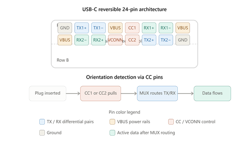
Reversible Dynamics: Engineering High-Speed Data and Power Delivery in USB-C Interfaces
A deep technical analysis of the USB Type-C connector specification, evaluating flippable pin matrices, configuration channels, EMI shielding, and high-wattage thermal dissipation.