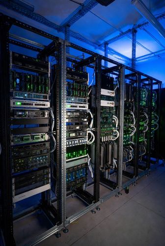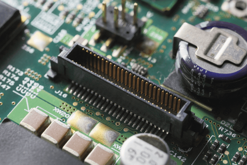
Backplane connectors exist to serve one specific mechanical scenario: a modular blade or card being plugged into a central chassis by a technician who cannot see the connector at the moment it actually mates. This is standard operating procedure in telecommunications and data center hardware, where high availability and fast field maintenance are non-negotiable requirements — and it demands a genuinely different engineering approach than any connector a person assembles while looking directly at it.
Blind-Mating and Alignment
Since the connector itself is invisible during insertion, the mechanical system has to guide itself into alignment before the electrical pins ever make contact. Two features do this work.
Guide pins are long metal or plastic posts, longer than the electrical contacts themselves, that engage first and physically steer the blade into rough alignment before a single signal pin is at risk of touching anything. This staged engagement — mechanical alignment first, electrical contact second — is what prevents a technician's imprecise, by-feel insertion from bending delicate high-pin-count contacts.
Floating housings give the connector itself a few millimeters of lateral play, letting the pin field center itself into its mating socket even when the guide pins alone haven't achieved perfect alignment. This is, functionally, the same underlying engineering principle covered in depth in our floating connector design guide — the same X/Y compliance that protects a floating board-to-board connector from misalignment and thermal expansion is what lets a backplane connector self-correct as a heavy blade is pushed home.
Managing High Pin Counts and Insertion Force
A single backplane connector can carry more than 500 pins, and that density creates a very real mechanical problem: the cumulative insertion force required to seat 500 pins into 500 sockets simultaneously can exceed 50 pounds. That's not a trivial number — it's enough force to damage a PCB or injure a technician if the mechanical system isn't specifically engineered to manage it.
Two techniques address this directly. Press-fit (compliant pin) technology changes how the connector's pins terminate to the PCB itself, using a pin geometry that deforms slightly on insertion to create a reliable gas-tight connection without requiring solder — this reduces the precision demands on the insertion process itself compared to a solder-only interface. Separately, leverage-assisted handles built into the blade's mechanical design let a technician apply the full seating force through a mechanical advantage, rather than relying on raw hand strength to push a 500-pin connector home evenly and without damage.
Why This Matters Beyond the Connector Itself
Getting blind-mate mechanics right isn't a nice-to-have refinement — it's what actually makes hot-swappable, field-serviceable blade architecture viable at all. A backplane connector that requires visual alignment or excessive insertion care defeats the entire purpose of a blade system, which is fast, low-skill field replacement. The broader architectural context this mechanical design serves — passive vs. active backplane topology, and the signal integrity demands driving modern blade server design — is covered in our server backplane architecture guide.