The Reality of Cumulative Tolerances
In a perfect computer-aided design (CAD) environment, components align flawlessly down to the nanometer. In the real world of high-volume manufacturing, engineers run into the problem of tolerance stacking. When multiple board-to-board connectors are populated onto a single PCB, or when rigid PCBs are mounted into cast aluminum enclosures, minor variations in SMT component placement, screw-hole drilling, and structural housing dimensions add up.
If a designer attempts to mate multiple standard, rigid board-to-board connectors simultaneously across two stiff PCBs, any spatial offset will generate severe, continuous mechanical stress. This stress warps the substrate, shears copper traces, and cracks solder joints. To solve this problem without requiring unrealistically expensive machining tolerances, engineers specify floating board-to-board connectors.
The Kinematics of Floating Mechanisms
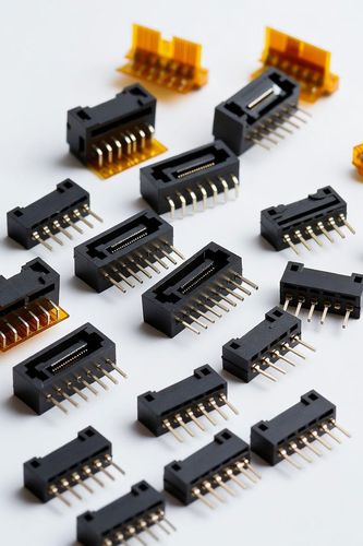
A floating connector features an internal mechanical decoupling layer. The connector is split into two distinct sub-structures: a rigid base that is permanently soldered to the PCB, and a dynamic, movable mating interface that can shift independently of the base.
Multi-Axis Compliance
High-performance floating connectors provide true three-dimensional compliance, typically calculated across three primary axes:
- X-Axis (Transverse) Float: Absorbs left-to-right lateral offsets, typically allowing +/-0.5 mm to +/-1.0 mm of movement.
- Y-Axis (Axial) Float: Absorbs front-to-back longitudinal shifts, offering matching tolerances to handle component placement drift.
- Z-Axis (Vertical) Tolerance: Manages stack-height variations and structural bowing across the span of the PCB.
Spring Contact Geometry
The magic of the float occurs within the contact architecture itself. Instead of a stiff metal pin, a floating connector utilizes highly engineered, flexible, dual-point spring contacts (often forged from high-elasticity Beryllium Copper). These contacts act as miniature suspension springs. They bend and flex to absorb the mechanical offset of the housing while maintaining a constant, predictable normal force against the mated pin, ensuring zero loss of electrical continuity.
Manufacturing Advantages in Automated Assembly
- Blind Mating Support: In automated assembly lines where modules are slammed together by robotic arms without visual confirmation, the floating connector's chamfered entry guides capture the offset plug and slide it into alignment, protecting the contacts from crushing.
- Multiple Connector Population: Traditional engineering rules state that you should never use more than one board-to-board connector pair between two rigid PCBs due to alignment conflicts. Floating connectors break this restriction. By using one rigid connector as the absolute datum anchor and populating secondary lines with floating connectors, engineers can deploy multiple board-to-board interfaces across the same substrate without risking board stress.
Electrical and Signal Integrity Challenges of Floating Contacts
While floating mechanisms provide exceptional mechanical relief, they present a unique set of challenges for electrical signal integrity engineers.
Because the internal contacts must contain extended, flexible loops to allow for physical movement, the overall electrical path length is significantly longer than that of a standard, straight-line connector. This added physical length directly introduces:
- Increased Inductance: Longer paths mean higher loop inductance, which can degrade high-speed signal edges.
- Impedance Discontinuities: The complex bending geometries of the spring contacts create variations in the cross-sectional distance between adjacent lines, generating capacitance spikes that cause signal reflections.
To counter this, advanced floating connectors incorporate grounding shields that wrap around the flexible spring elements, tuning the capacitive-to-inductive ratio to maintain a stable 100 Ohm differential impedance profile, even when the connector is floating at its maximum mechanical displacement.
Mitigating Structural Fatigue
Floating board-to-board connectors demonstrate that the most elegant solution to mechanical rigidity is controlled compliance. By embedding micro-spring kinematics straight into the contact and housing architecture, these components absorb the realities of factory tolerance stackups. They protect solder points from structural fatigue and enable multi-connector configurations that would be impossible with traditional rigid interconnects.