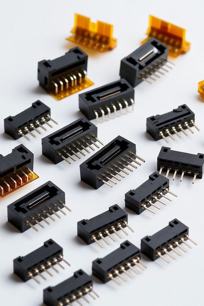
The Open Compute Project (OCP) Data Center Secure Control Module (DC-SCM) specification fundamentally changes data center motherboard architecture by decoupling server management, security, and control functions from the primary compute baseboard. Traditionally, the Baseboard Management Controller (BMC), Hardware Root of Trust (RoT), firmware SPI flashes, and monitoring circuitry were soldered directly onto the server motherboard. This coupled the lifecycle of management silicon to the x86 or ARM host CPU platform, forcing complete redesigns of management subsystems with every host processor generation.
DC-SCM establishes a standardized, pluggable module that houses the BMC, RoT, management memory, and peripheral logic. By shifting these systems to an independent module, hardware manufacturers can standardize their security and management infrastructure across diverse CPU platforms, drastically lowering development cycles and firmware fragmentation. At the heart of this specification is the physical DC-SCM connector interface, a high-density, multi-bus connector that bridges the control module to the main processor board (HPM, or Host Processor Mainboard).
The DC-SCM Physical Connector Interface
The physical interface between the DC-SCM module and the HPM is defined around a standardized high-speed board-to-board connector: an SFF-TA-1002 compliant 4C+ connector, a 4C-compliant connector with an additional 28-pin OCP bay as defined in the OCP NIC 3.0 specification, for a total of 168 contacts. This connector family is engineered for low latency, high signal integrity, and mechanical resilience.
The connector carries a combination of high-speed management signals, low-speed legacy control buses, low-voltage power rails, and dedicated security control lines:
- High-Speed Bus Interfaces: PCIe lanes for fast BMC-to-Host communication, NC-SI (Network Controller Sideband Interface) for out-of-band management networking, and dedicated USB signals for local debugging and media redirection.
- Low-Speed Control & Telemetry: SPI/eSPI buses for flash access, I2C/SMBus/I3C channels for sensor monitoring and PMBus power management, along with dedicated GPIOs for system power sequencing and reset states.
- Security & RoT Signals: Dedicated traces for RoT verification, hardware tamper detection lines, physical intrusion detection, and cryptographic boundary signals.
- Power Distribution: Auxiliary power rails (3.3V_AUX and 12V_AUX) supplied from the mainboard to power the BMC and RoT before main system power sequencing initiates.
                      DC-SCM MODULE
  [BMC]  |  [Root of Trust]  |  [eSPI / Flash]  |  [Sensors]
                              ||
        Standardized High-Density Interface (168-pin, SFF-TA-1002 4C+)
                              ||
                HOST PROCESSOR MAINBOARD (HPM)
  [Host CPU 0]    |    [Host CPU 1]    |    [Power Stages]
Key Mechanical Retention and Orientation Features
Because DC-SCM modules are deployed in dense rack environments subject to thermal stress and vibration during service, the connector specification enforces rigorous mechanical retention and alignment rules:
- Polarization Keys: The physical connector housing incorporates mechanical keying to prevent upside-down or misaligned insertion, protecting sensitive low-voltage signaling pins from accidental exposure to power rails.
- Staged Contact Pin Lengths: Pins are arranged with staggered contact lengths (first-mate, last-break) to enable safe sequenced power handling during module mating. Ground contacts mate first to discharge static accumulation before logic lines make contact.
- Latch & Guide Systems: Physical retention brackets and guide pins ensure that insertion forces are distributed evenly across the surface-mount solder pads on both the DC-SCM card edge and the host baseboard.
Engineering Integration and Layout Pitfalls
Integrating a DC-SCM connector interface into a host server baseboard introduces specific layout and signal routing challenges:
- Signal Crosstalk & Trace Skew: High-speed signals like eSPI and PCIe running parallel to high-current auxiliary power pins require minimum ground shielding clearances to prevent noise coupling into sensitive reset lines.
- Keep-Out Zones (KOZ): Thermal clearances surrounding the DC-SCM slot must be strictly enforced. Placing high-dissipation components upstream in the airflow path can cause thermal throttling on the DC-SCM BMC or RoT processor.
- Coplanarity Issues: Due to the fine pitch of high-density edge connectors, solder paste application and PCB planarity are critical during surface-mount manufacturing to eliminate open joints.
Decoupling management silicon via DC-SCM streamlines operational security and simplifies platform hardware upgrades across Open Compute Project server fleets.
Where to Go Deeper
See the Application Spotlight: Choosing Connectors for an OCP ORv3 AI Accelerator Rack for a full walkthrough of how this standard works together with the other OCP interconnects in a single AI rack build.