In modern enterprise data centers, the server backplane is the silent, foundational backbone underneath every blade server deployment. As cloud computing, AI workloads, and large-scale database management push data throughput demands higher every generation, the backplane's job — routing data, distributing power, and managing control signals between hot-swappable compute blades and the core chassis infrastructure — has gone from a commodity design problem to a genuinely difficult one.
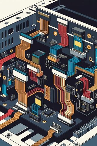
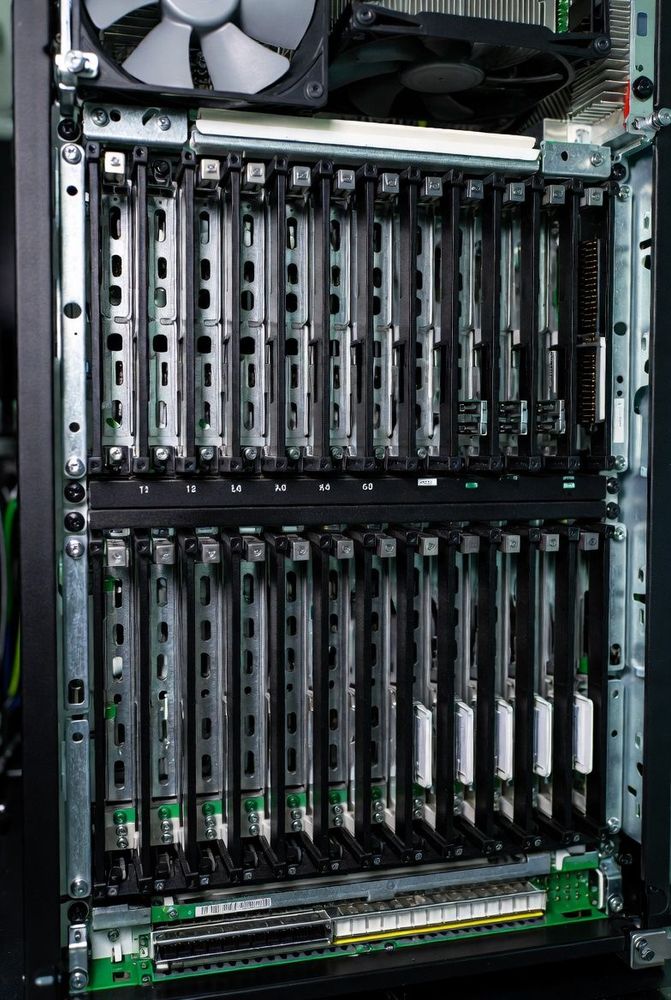
A server backplane, at its core, is a specialized circuit board mounted at the rear of a server chassis, populated with high-density connectors that accept compute modules, storage drives, and power supplies. Its primary architectural value is eliminating internal wiring harnesses entirely: instead of a tangle of cables running between components, every blade connects directly into the backplane's PCB traces. That elimination isn't just tidiness — it directly reduces the physical clutter that blocks airflow, and airflow is one of the tightest constraints in high-density compute.
Passive vs. Active Backplane Topology
There are two fundamentally different design philosophies for a backplane, and the choice between them shapes the reliability and scaling characteristics of the entire system.
Passive backplanes contain essentially no active circuitry — they rely strictly on physical copper traces and high-speed connectors to route signals, with no switches, bridges, or buffer chips in the signal path. That absence of active components is precisely what gives passive designs their defining advantage: exceptionally high reliability and low thermal output, since there's simply nothing on the backplane itself to fail or generate heat. This is why passive backplanes remain the standard choice in modular blade server designs where uptime is the priority.
Active backplanes integrate onboard silicon — PCIe switches, SAS/SATA expanders, or buffer chips — directly into the backplane itself. This introduces genuine tradeoffs: more potential points of failure, and more heat generated on a board that's already thermally constrained. In exchange, active components let a limited set of system resources fan out to a much larger array of expansion drives or compute nodes than a purely passive design could support. The choice between the two isn't a matter of one being categorically better — it's a direct tradeoff between maximum reliability and maximum resource-scaling flexibility.
Why Blade Architecture Exists At All
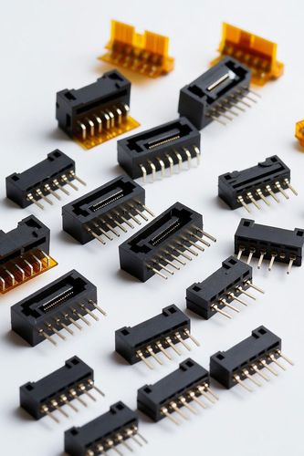
The move toward dedicated blade server backplanes was driven by computational density, not aesthetics. A standard rack-mount deployment requires every individual server to carry its own dedicated power supply, cooling fans, and network cabling — redundancy that adds up fast at scale. Blade architecture aggregates all of that shared infrastructure into a single centralized chassis, with the backplane acting as the central clearinghouse. When a blade is slotted into place, its blind-mate connectors engage the backplane automatically, and within milliseconds the blade is live on the shared power bus, the management controller network, and the high-speed data fabric — whether that fabric is 100G/400G Ethernet, InfiniBand, or PCIe Gen 6.
Signal Integrity at 32-64 Gbps and Beyond
As per-lane data rates push past 32 Gbps and toward 64 Gbps, maintaining signal integrity across a physical PCB backplane becomes a genuinely hard electrical engineering problem, not just a mechanical one. Three physical effects dominate the challenge:
Insertion loss and attenuation — high-frequency signals degrade rapidly across standard FR4 PCB material, which is why high-end backplanes lean on advanced low-loss dielectric laminates to preserve signal strength over the board's full length.
Crosstalk — with thousands of high-speed traces routed in close parallel proximity, electromagnetic interference between adjacent channels is a constant risk. Backplane designers combat this with dedicated shielding layers, continuous ground planes, and carefully optimized differential pair routing to keep critical signal paths isolated from their neighbors.
Impedance matching — any discontinuity in trace geometry or at a connector interface reflects signal energy back toward the source, corrupting data. Maintaining a precise, unbroken differential impedance from the blade's edge connector all the way through to the switch fabric is non-negotiable at these speeds.
Where the Mechanical and Electrical Pieces Fit Together
This architectural overview covers the backplane at the system level — but two more specific engineering problems sit underneath it, each substantial enough to warrant their own treatment. The mechanical side of making a blade slot blindly into a backplane without a technician ever seeing the connector is covered in our piece on blind-mate backplane connectors, guide pins, and insertion force management. The connector-level electrical design that actually achieves the signal integrity targets described above — ground plane geometry, stack height selection, and cross-vendor intermateability — is covered in our guide to engineering high-speed board-to-board connector interfaces.
The lead times and sourcing pressure on the specialized backplane connectors this architecture depends on are also worth understanding before committing to a design — our piece on supply chain bifurcation and transceiver lead times covers exactly why these high-density components can carry 40+ week lead times even as commodity connectors remain readily available.