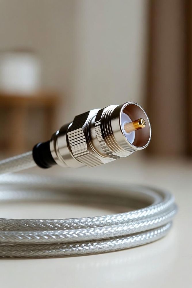
"It mates" is a low bar
The second-sourcing article already draws the distinction between true intermateability and simple form-fit-function similarity. This piece is the follow-through on that distinction: the actual mechanical and electrical checks that separate "this connector physically plugs into the same mating half" from "this connector is genuinely qualified to replace the original in production."
Datasheet comparison alone checks pitch, pin count, and outline dimensions — because those are the easiest properties to compare from a distance, and the ones distributor parametric search tools filter on. None of them confirm that a candidate connector performs equivalently once it's actually carrying current, flexing under vibration, or being mated and unmated hundreds of times over a product's service life.
Contact normal force
Contact normal force is the spring force a contact exerts against its mating pin once engaged, and it's arguably the single most consequential property that a pitch/pin-count comparison completely misses. Two connectors can use contacts with identical outer geometry and still have meaningfully different spring designs behind that geometry — a different beam length, a different spring material temper, a different number of contact points — and normal force directly drives three things that matter over the life of the product: initial and long-term contact resistance stability, wear life across repeated mating cycles, and resistance to contact chatter under vibration. A candidate connector with lower normal force than the original can look identical on a table of dimensions and still develop resistance drift or intermittent contact years sooner in the field.
Insertion and extraction force
For any connector that's hand-mated — during assembly, field service, or repair — insertion and extraction force is a manufacturability and serviceability spec, not just a comfort detail. A "compatible" alternate with meaningfully higher insertion force can fail an assembly line's ergonomic or cycle-time process spec even when it performs identically once mated, and this is a failure mode that typically doesn't surface until a first-article line trial — well after a paper qualification has already been signed off. It's worth requesting actual insertion/extraction force test data (most connector manufacturers publish or can provide it) rather than assuming force scales predictably with connector size or pin count.
Pin and socket tolerance stack-up
Contact pin diameter and socket bore diameter both carry manufacturing tolerances, and those tolerances interact multiplicatively across every mating pair in a connector, not just once. Two connectors with identical nominal dimensions can land at opposite ends of the practical fit range: a stack-up that runs tight produces excess insertion force and accelerated contact wear, while a stack-up that runs loose produces unstable contact and a real risk of fretting corrosion — micro-motion between loosely mated contact surfaces that gradually oxidizes the contact interface and raises resistance over time, often the actual root cause behind an "intermittent connection" field complaint that shows no obvious damage on visual inspection. Nominal-dimension matching says nothing about which end of the tolerance range a specific manufacturer's process actually lands on.
Dielectric withstand and creepage/clearance
For any application above low-voltage signal levels, insulator material and internal contact spacing determine actual dielectric withstand voltage — and two connectors that match on current rating can still differ meaningfully here if one uses a different insulating resin or a tighter internal contact-to-contact or contact-to-shell spacing to achieve a smaller overall footprint. This is a genuine safety and compliance parameter, not just a performance one, and it's worth explicitly requesting dielectric withstand and creepage/clearance figures for any candidate alternate intended for a higher-voltage application, rather than inferring adequacy from current rating alone.
Current rating and thermal rise under load
Current rating comparisons are usually more visible than the checks above since they're a standard datasheet line item — but the number that actually matters in practice is temperature rise under the connector's real operating current in the real enclosure/harness context, not the rated figure in isolation. The site's cable temperature rating and derating guide covers this derating logic in depth for the cable side of an assembly; the same underlying principle — rated capacity assumes specific ambient and duty-cycle conditions that a real application may not match — applies to the connector's own contact and housing thermal limits as well.
A practical verification protocol
None of the checks above require exotic test equipment to at least partially verify:
Request the actual test report, not just a datasheet summary, for contact normal force, insertion/extraction force, and mating durability (cycle life) — most connector manufacturers can provide this on request even when it isn't published.
Physically mate and unmate a sample of the candidate connector against your actual mating half — not a generic reference part — before committing, since fit issues specific to a particular mating pair combination won't show up comparing either connector against its own datasheet in isolation.
For a high-criticality or high-volume application, budget for an actual sample-lot test: contact resistance measured before and after a representative number of mating cycles, rather than relying purely on a datasheet-to-datasheet comparison. This is exactly the kind of verification step that separates a BOM risk register entry marked "known alternates identified: yes" as a genuinely tested claim, rather than "looks similar on paper."
A connector that shares pitch, pin count, and outline with the original has cleared the easiest bar, not the real one. The properties that actually determine whether a second source performs equivalently over a product's service life — contact normal force, tolerance stack-up, dielectric margin, and thermal behavior under real load — live inside the connector, not on the outline drawing, and none of them are visible from a parametric search filter alone.
Qualifying a specific cross-referenced connector and not sure which of these checks actually matters for your application? Ask the Engineer — real questions from real designs get answered.