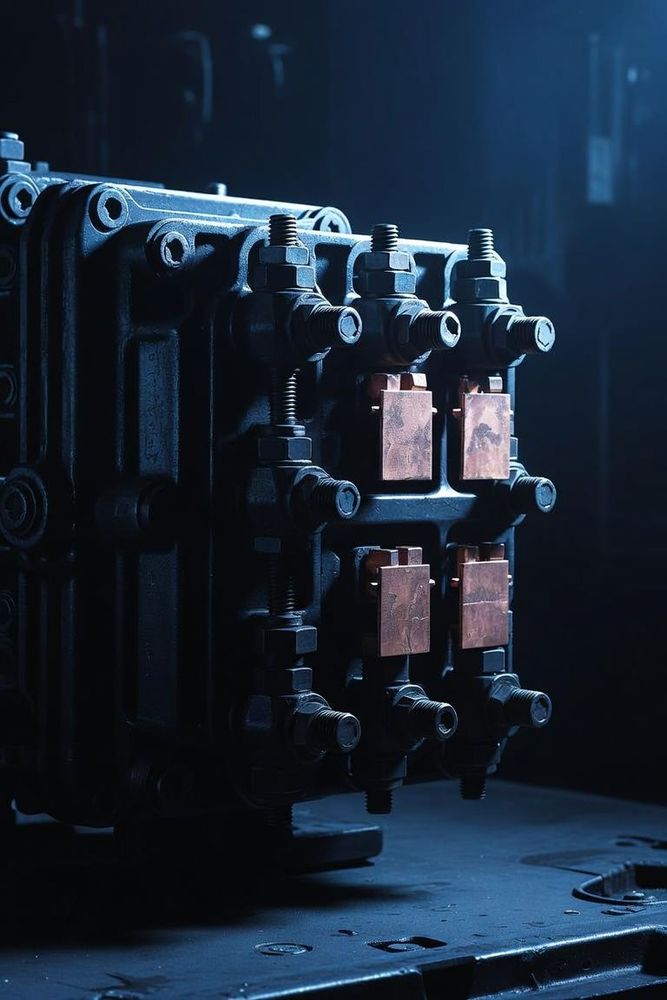
Defining Electrical Boundaries
Every electrical connector is designed with fixed limits regarding the amount of electrical energy it can safely handle. Exceeding these boundaries risks circuit failure, insulation melting, or electrical fires.
These limits are defined by two key parameters: Current Rating (expressed in Amperes) and Voltage Rating (expressed in Volts). While both numbers dictate power handling, they are governed by entirely different physical phenomena within the connector assembly.
Understanding Current Rating (Ampacity)
The current rating represents the maximum volume of electrical current that can continuously flow through a connector contact without causing the component to overheat or degrade.
The Physics: Joule Heating
When current passes through a metal contact, it encounters a small amount of electrical resistance, known as contact resistance (R). According to Joule's first law, this resistance converts a portion of the electrical energy into thermal energy: P = I² × R, where P is power dissipated as heat (Watts), I is current (Amps), and R is contact resistance (Ohms). Because the heat generated scales exponentially with the square of the current, doubling the amperage increases the heat output by four times.
How Manufacturers Determine Current Limits
Manufacturers evaluate current limits based on a specified temperature rise (ΔT), typically a 30°C increase above ambient room temperature. If a contact's temperature climbs beyond its maximum rated operating temperature (often 105°C to 125°C for standard plastics), the plastic housing will soften, lose structural integrity, and fail to hold the contacts in place.
Understanding Voltage Rating
While the current rating focuses on thermal limits inside the conductors, the voltage rating focuses on the insulation capabilities of the housing material and the spatial gaps between contacts.
The voltage rating represents the maximum electrical potential difference that can exist between two adjacent contacts, or between a contact and a grounded metal shell, without risking an insulation breakdown.
The Mechanics of Voltage Failure
- Dielectric Breakdown: If the voltage exceeds the insulating capability of the plastic housing material, the voltage will punch through the plastic, destroying the insulator and creating a direct short circuit.
- Clearance Distance: The shortest path through the air between two conductive elements. If voltage is too high for a given clearance, the air can ionize, causing an arc flash across the gap.
- Creepage Distance: The shortest path along the physical surface of the insulating plastic between two contacts. Over time, dust and moisture can accumulate on the physical surface, creating a conductive tracking path for current to crawl across.
The Critical Role of Derating
A connector's advertised maximum specifications are determined under ideal laboratory conditions. In real-world deployments, engineers must apply derating—reducing the allowed operating limits based on ambient environmental factors to ensure an adequate safety margin.
1. Ambient Operating Temperature
If a connector is rated for 5 Amps at a room temperature of 25°C, it cannot safely carry that same 5 Amps inside an uncooled automotive engine bay running at 85°C. The baseline temperature is already high, leaving less headroom for the thermal rise before reaching the plastic's melting threshold. Designers utilize manufacturer-provided derating curves to see exactly how much current must be scaled back as ambient heat increases.
2. Multi-Circuit Loading
Current ratings are often published based on a single isolated contact carrying current. When an entire block or multi-pin layout is fully populated and all pins carry maximum current simultaneously, the heat from adjacent pins builds up, trapping thermal energy within the center of the housing. In multi-pin configurations, the current allowed per pin must be derated significantly compared to a single-line configuration.
3. Environmental Conditions (Altitude and Humidity)
At higher altitudes, the air becomes thinner and acts as a less effective electrical insulator and thermal cooling agent. Consequently, connectors deployed in aerospace applications must be derated for both voltage and current to prevent high-altitude arcing and excessive heat retention.