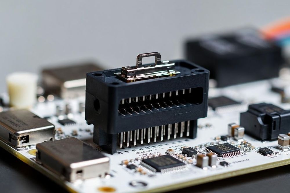
The Critical Role of FPC Connectors in Compact Hardware
Flexible Printed Circuit (FPC) connectors serve as the mechanical and electrical bridge between flexible circuits and rigid mainboards. In space-constrained electronics such as smartphones, wearables, medical probes, and automotive displays, choosing the wrong FPC connector leads to cable pull-out, intermittent signal continuity, assembly line yield losses, or damaged contact beams during factory rework.
Hardware engineers must evaluate multiple mechanical, electrical, and manufacturing parameters to select the optimum FPC connector for their application.
Step 1: Choose the Actuator Type (ZIF vs. LIF)
The mechanical locking mechanism of an FPC connector defines its assembly process and mechanical robustness:
Zero Insertion Force (ZIF) Connectors
ZIF connectors feature a movable mechanical latch (actuator) that opens to allow the FPC cable to slide into the housing without resistance, preventing friction wear on the contact pads. Closing the latch compresses internal spring beams against the cable pads.
- Flip-Lock / Back-Flip Actuators: The actuator rotates on a hinge to lock the cable in place. Back-flip designs are preferred for automated assembly because the latch opens away from the insertion slot, preventing accidental closure during automated cable insertion.
- Slider / Push-Pull Actuators: A sliding collar is pulled out to open the slot and pushed back in to lock. They offer robust mechanical locking but require two-handed operation or specialized assembly tools.
Low Insertion Force (LIF) Connectors
LIF connectors have no moving actuator. The FPC cable is pushed directly into a friction-fit slot, where wiping contacts hold it in place.
Trade-Offs: LIF connectors are lower cost, lower profile, and feature fewer moving parts to break during assembly. However, they offer significantly lower cable retention force and accelerate plating wear over multiple insertion cycles, making them suitable only for low-pin-count, static internal connections.
Step 2: Determine Contact Position (Top, Bottom, or Dual)
FPC connector spring contacts sit on a specific internal wall inside the connector housing. Matching the connector contact orientation to the cable's conductive surface is critical:
- Top Contact Connectors: The spring beams rest on the top inner roof of the housing. The FPC cable must enter with its exposed copper pads facing upward.
- Bottom Contact Connectors: The spring beams reside on the floor of the housing. The FPC cable must enter with its exposed copper pads facing downward.
- Dual Contact / Dual Beam Connectors: Internal spring contacts sit on both the top and bottom walls, electrically connected together. Dual contact connectors accept FPC cables with pads facing either direction, eliminating cable orientation errors on the assembly line and increasing contact redundancy under vibration.
Step 3: Match Mechanical Stiffener Thickness
FPC connectors are engineered to operate with an FPC cable end of a precise total thickness—most commonly 0.30mm ±0.03mm or 0.20mm ±0.03mm.
This nominal thickness is achieved by laminating a plastic stiffener (polyimide or FR4) behind the flex circuit's coverlay and copper layers. If the stiffener is too thin, the connector's spring contacts cannot generate sufficient normal force, causing high contact resistance and intermittent disconnections. If the stiffener is too thick, forcing the cable into the connector bends or breaks the delicate internal contact beams.
Step 4: Evaluate Mechanical Retention Features
In high-vibration environments or applications subject to drop impacts, simple friction contact is insufficient to hold the flex cable in place:
- Side Catcher / Tab Locks: Many high-reliability FPC connectors feature plastic side ears or metal side latches that engage molded ears (notches) on the sides of the FPC cable. When the actuator closes, these tabs mechanically lock the flex circuit in place, providing high resistance to axial pull-out forces.
- Anchoring SMT Soldertabs: Ensure the connector housing incorporates wide, robust metal solder tabs (hold-downs) on both ends of the body. These tabs anchor the plastic housing to the PCB, absorbing mechanical peel forces applied when the flexible cable is flexed or pulled.