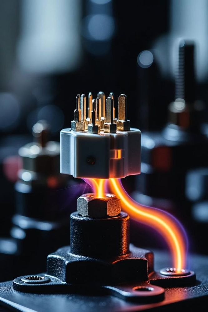
Demystifying Datasheet Current Ratings
One of the most dangerous assumptions a hardware designer can make is taking a connector's datasheet current rating at face value. A spec sheet claiming "10 Amps per contact" does not mean you can safely pass 10A through every pin of a 20-position connector inside a fully enclosed chassis at 85°C.
In reality, connector current capacity is limited entirely by temperature rise. Overloading a connector causes resistive heating that can melt plastic housings, degrade contact spring tension, and ignite circuit assemblies.
How Manufacturers Determine Current Ratings (EIA-364-70)
Under standard test methods like EIA-364-70, manufacturers determine a connector's current rating by applying current to contacts and measuring the temperature rise above ambient. The standard threshold for maximum current capacity is typically set at the point where localized contact heating causes a 30°C temperature rise above room temperature (25°C).
However, these laboratory test conditions rarely mirror real-world embedded hardware implementations:
- Single-Contact vs. Fully Energized Housing: Tests are often conducted with only one or a few isolated contacts carrying current, allowing adjacent plastic and metal to act as heat sinks.
- Open-Air Testing: Tests occur in open, still air, whereas your PCB might reside inside a tightly sealed, fanless IP67 enclosure.
- Heavy Gauge Test Conductors: Lab setups often solder unnaturally thick copper wires to test pins to pull heat away from the contacts during testing.
The Essential Rule: Applying Thermal Derating Curves
To ensure safety and reliability, hardware engineers must apply thermal derating based on three key system variables: pin density, ambient operating temperature, and PCB copper mass.
1. Multi-Position Heating Factor
When multiple adjacent pins carry heavy current simultaneously, heat cannot dissipate effectively. The internal contacts trap thermal energy inside the insulating plastic shell. As a rule of thumb, when energizing more than 50% of the positions in a high-density connector, reduce the maximum rated current per pin by 20% to 40%.
2. Ambient Temperature Derating
If your product operates in an industrial cabinet at an ambient temperature of 70°C and your connector housing material is rated for a maximum operating temperature of 105°C, your maximum allowable temperature rise is reduced to just 35°C (105°C minus 70°C). Always consult the manufacturer's Current Carrying Capacity Curve (or T-Rise curve) to determine the exact current limit at your target ambient temperature.
3. PCB Copper Mass and Heat Sinking
The primary heat sink for a surface-mount or through-hole connector contact is the copper trace and plane system on your PCB. If you attempt to feed a 10A connector pin using a narrow 10-mil trace with standard 1-ounce copper, the trace itself will heat up and transfer heat into the connector.
Layout Best Practices for High-Current Connectors
When designing high-current power input interfaces on your PCB:
- Pour Generous Copper Planes: Connect power pins directly to wide, thick copper pours (2-ounce or 3-ounce copper preferred for high-power boards) on both top and internal layers.
- Use Multiple Thermal Vias: Place arrays of thermal stitching vias immediately adjacent to SMT power pads to pull heat down into internal ground and power planes.
- Gang Pins for Power Rails: If a single pin cannot handle the required current, group 3 or 4 adjacent pins together on the same power rail. Ensure the layout splits trace paths symmetrically so current distributes evenly across all pins rather than crowding into the path of least resistance.