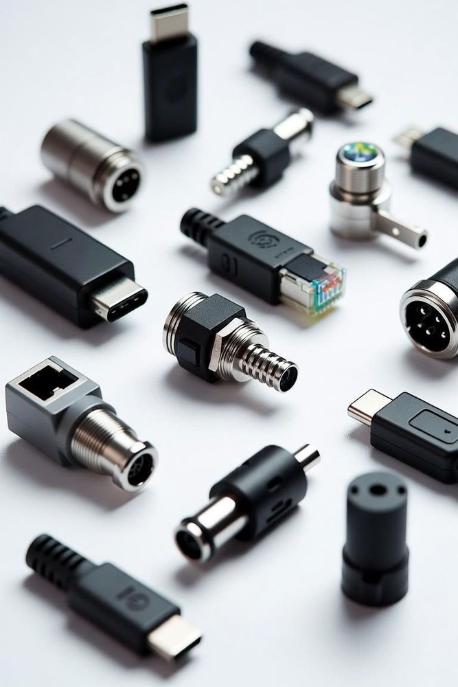
Introduction to Electrical Connectors
At its core, an electrical connector is an electromechanical device used to join electrical conductors and create a continuous electronic circuit. While the concept sounds simple, the execution requires a delicate balance of materials science, mechanical engineering, and electrical physics. Connectors allow systems to be modular, serviceable, and scalable. Without them, every component in an electronic device would need to be permanently soldered or hardwired, making manufacturing, upgrades, and repairs incredibly inefficient.
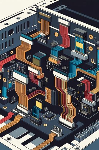
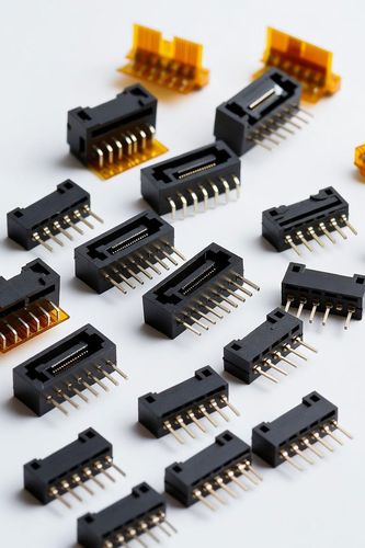
Connectors are used everywhere—from the micro-miniature flexible printed circuit (FPC) connectors inside smartphones to massive, heavy-duty industrial plugs supplying high-voltage power to factory machinery. Understanding the fundamentals of how these components function is essential for anyone designing, maintaining, or working with electronic systems.
Core Functions of an Interconnect
An electrical connector must perform three primary functions simultaneously to ensure system reliability:
- Electrical Continuity: The primary task is to transfer electrical current or signals from one subsystem to another with minimal resistance. Any added resistance at the connection point causes signal degradation or localized heating.
- Mechanical Integrity: Connectors must establish and maintain a secure physical bond. They must withstand environmental forces such as vibration, shock, tensile stress, and thermal expansion without decoupling or losing contact pressure.
- Environmental Isolation: Depending on the application, a connector may need to protect the sensitive electrical contact area from dust, moisture, corrosive gases, and extreme temperatures to prevent oxidation and eventual failure.
Temporary vs. Permanent Connections
While some electrical joints are intended to remain undisturbed for the lifespan of a product, others require frequent decoupling. Connectors are generally categorized by their intended operational lifecycle:
Permanent and Semi-Permanent Joints
These are connections meant to stay joined long-term. Examples include terminal blocks with screw clamps, wire nuts, or insulation displacement connectors (IDC) used in telecom wiring. While they can technically be disassembled, doing so often requires tools or damages the wire end, making them ill-suited for daily user interaction.
Matable / Disconnectable Connectors
These are designed for multiple insertion and extraction cycles. They feature mating interfaces that can be separated easily by hand or with simple latching mechanisms. Examples include USB ports, HDMI cables, barrel jacks, and circular aviation connectors. The internal contacts are engineered to slide against one another, maintaining reliable electrical contact across hundreds or thousands of mating cycles.
Classifications by Application
Connectors are broadly grouped based on where they reside within an electronic system architecture:
Level 1: Board-to-Board (B2B)
These solutions connect two printed circuit boards directly together without the use of intermediary cables. Examples include mezzanine connectors, PCIe slots, and edge cards.
Level 2: Wire-to-Board (W2B)
These configurations connect a discrete wire or ribbon cable bundle directly to a header mounted on a PCB. Examples include JST headers, Molex Mini-Fit series, and flexible flat cable (FFC) connectors.
Level 3: Wire-to-Wire (W2W)
These assemblies connect two discrete cables or wire harnesses together mid-run, completely isolated from a circuit board. Examples include Deutsch DT automotive series and standard crimp splices.
Level 4: Panel / Input-Output (I/O)
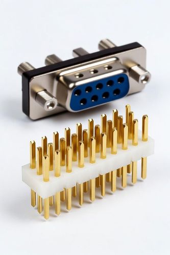
These are mounted directly to an enclosure wall or bulkhead to bridge internal system circuits with external user devices. Examples include XLR audio ports, RJ45 network jacks, USB-C chassis ports, and D-Subminiature interfaces.
Key Materials and Construction
The performance of an electrical connector relies on two distinct material types working together: the conductor and the insulator.
Contact Materials (Conductors)
Contacts are typically formed from copper alloys (such as brass, phosphor bronze, or beryllium copper) due to their excellent electrical conductivity and spring retention properties. Because copper alloys tarnish easily, they are usually electroplated with high-performance metals:
- Gold Plating: Offers exceptional corrosion resistance and excellent conductivity. Ideal for low-voltage signal lines where even minor oxidation can disrupt data.
- Tin Plating: A cost-effective choice for power connectors or high-pressure static connections. Tin is prone to fretting corrosion under vibration, making it less suitable for high-precision signals.
Housing Materials (Insulators)
The housing holds the contacts in precise alignment and prevents them from shorting against each other or the surrounding chassis. Housings are made from high-performance engineering plastics like Nylon, Liquid Crystal Polymer (LCP), Polybutylene Terephthalate (PBT), or Polyphenylene Sulfide (PPS). These plastics are selected for their high dielectric strength, thermal stability during soldering, and mechanical toughness.