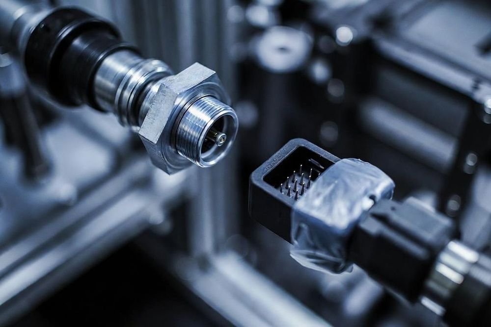
Understanding Connector Mating Cycles and Durability
In hardware engineering, a mating cycle represents a single complete insertion and extraction sequence of a connector pair. While some internal connectors are mated only once or twice during factory assembly, external user-facing ports—such as USB-C charging receptacles, battery interfaces, and diagnostic ports—must withstand thousands of cycles over the product's operational lifespan.
Specifying a connector without accounting for its mating cycle rating leads to intermittent electrical contacts, elevated contact resistance, plating wear, and premature product failure in the field.
Physical Mechanisms of Contact Wear
To design durable interfaces, hardware engineers must understand the physical and material degradation that occurs during repeated mating operations.
Plating Wear and Base Metal Exposure
Connector contacts are typically formed from copper alloys (such as phosphor bronze or beryllium copper) coated with a thin layer of precious or non-precious metal plating. Every insertion scrapes the male and female contact surfaces against one another. Over repeated cycles, this abrasive friction wears away the outer plating, exposing the underlying base copper alloy to atmospheric oxygen and moisture.
Fretting Corrosion and Oxidation
When base metals are exposed, atmospheric oxidation forms a micro-layer of non-conductive oxide on the contact interface. Under micro-vibrations or thermal expansion cycles, these oxide films fracture and reform, leading to fretting corrosion. This corrosion manifests as erratic voltage drops and micro-interruption in signal lines.
Loss of Normal Force and Mechanical Fatigue
Female contact beams act as tiny metallic springs designed to maintain continuous mechanical pressure—known as normal force—against the male pin. Over hundreds or thousands of mating cycles, repeated mechanical displacement causes material fatigue, reducing the spring force. Lower normal force increases contact resistance and makes the connection far more susceptible to physical vibration disconnects.
Material Selection: Gold vs. Tin vs. Selective Plating
Contact plating material is the single most influential factor in determining a connector's rated mating cycles.
Tin Plating: Low-Cost, Low-Cycle Applications
Typical Rating: 10 to 50 mating cycles.
Engineering Characteristics: Tin is soft, highly ductile, and prone to fretting corrosion under vibration. It requires high normal forces (typically over 100 grams per contact) to mechanically wipe through surface tin oxides during insertion. It is best reserved for static, internal board-to-board or wire-to-board connections that are rarely un-plugged.
Gold Plating: High-Durability, High-Reliability Applications
Typical Rating: 100 to 5,000+ mating cycles (depending on gold thickness).
Engineering Characteristics: Gold is a noble metal that does not oxidize in air. It provides extraordinarily low contact resistance and excellent wear resistance under low normal forces (20 to 50 grams). Gold plating thickness is measured in micro-inches or micrometers: flash gold (1 to 3 micro-inches) supports low cycles, whereas hard gold (30 micro-inches or more) supports thousands of heavy-duty cycles.
Selective Plating: Optimizing Cost and Performance
To balance performance and cost, engineers frequently specify selective plating. In this setup, critical contact mating zones are plated with hard gold over a nickel underplate, while the PCB solder tails receive tin plating for optimal solderability during SMT reflow.
Engineering Best Practices for Maximizing Mechanical Lifespan
When designing high-cycle interfaces into your hardware:
- Specify Guide Shrouds and Alignment Features: Pin stubbing during blind or angled mating rapidly damages contact spring beams. Incorporate plastic guide posts, chamfered entry funnels, or metal shell shrouds to align the connectors before the internal contacts touch.
- Calculate Mating and Unmating Forces: Multi-pin high-durability connectors can require substantial insertion force. Calculate total insertion force (pin count multiplied by per-pin insertion force) to ensure user ergonomics and prevent PCB flexing or solder joint cracking during connection.
- Incorporate Environmental Sealing: Dust and abrasive particles accelerate plating wear during mating cycles. Sealed housings (IP67 or higher) keep gritty debris away from contact surfaces, extending mechanical wear life.