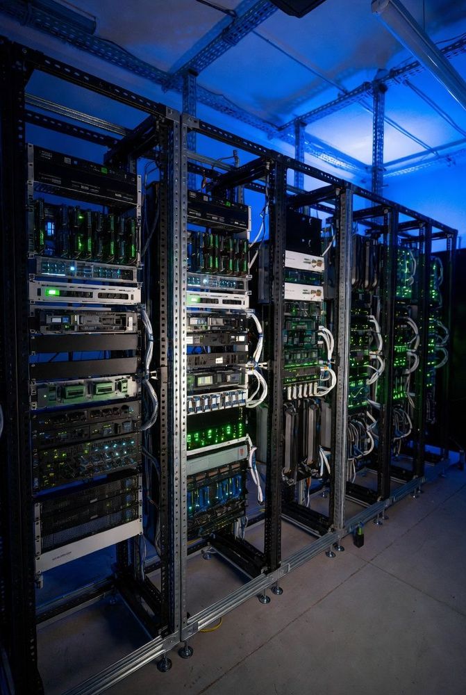
AI data center racks are outgrowing traditional power distribution. Multi-kW GPU accelerators, dense optical fabrics and high-core-count host processors are pushing rack power from tens of kilowatts toward hundreds. NVIDIA has described a move from conventional AC distribution to 800 VDC for its next-generation AI factories, with a long list of power-system partners including Delta, Vertiv, Schneider Electric, Eaton, ABB, Hitachi Energy, Infineon and Texas Instruments.
For connector engineers, the voltage change is the story. Going from 48V to 800 VDC cuts the current dramatically, but it replaces a high-current problem with a high-voltage insulation and safety problem.
In short:
- Delivering the same power at 800 V needs about one-seventeenth of the current needed at 48 V.
- Resistive loss in the same conductor falls by more than 99%.
- The connector problem shifts from heat and contact force to creepage, clearance, arc safety and insulation materials.
What NVIDIA Has Said
NVIDIA's 800 VDC announcement describes the following:
- The shift is from traditional 415 or 480 VAC three-phase distribution to 800 VDC.
- Over 150% more power can be transmitted through the same copper, which NVIDIA says eliminates the need for 200-kg copper busbars per rack.
- Kyber, the successor to the Oberon rack, moves from 54 VDC in-rack components to 800 VDC, and is planned to house 576 Rubin Ultra GPUs by 2027.
- The Vera Rubin NVL72 rack uses 45°C liquid cooling and a liquid-cooled busbar.
The post we reviewed does not publish connector specifications for 800 VDC racks.
The Physics: Why Higher Voltage Helps
Power is voltage times current, and resistive loss is current squared times resistance. As an illustration, take a 600 kW rack. This is a scale comparison, not a published NVIDIA figure.
- At 48 V: 600,000 W ÷ 48 V = 12,500 A.
- At 800 V: 600,000 W ÷ 800 V = 750 A.
That is a 94% drop in current. For the same conductor, resistive loss scales with current squared, so (750 ÷ 12,500)² = 0.36% of the original loss, a reduction of more than 99%. Nobody would build a single 12,500 A busbar. The comparison shows why designers cannot simply scale 48V distribution to these power levels.
- Current — 48 V DC: 12,500 A; 800 V DC: 750 A
- Relative busbar I²R loss, same conductor — 48 V DC: 100%; 800 V DC: about 0.36%
- Main hazard — 48 V DC: High current and heating; 800 V DC: High voltage, insulation and arcing
- Insulation rules — 48 V DC: Extra-low-voltage regime (around 60 V DC); 800 V DC: Creepage and clearance per IEC 60664-1 and UL 840
Lower current means smaller conductors, lighter busbars and lower contact forces, which frees space for compute blades and liquid-cooling manifolds.
Connector Implications
1. Creepage and clearance
Two distances govern insulation safety in a high-voltage connector:
- Clearance: the shortest distance through air between two conductive parts.
- Creepage: the shortest distance along the surface of an insulating material between two conductive parts.
   [ HV Pin 1 (+800 V) ]                      [ HV Pin 2 (GND) ]
         |                                           |
         |======== Clearance (air distance) =========|
         |                                           |
         +-----\                               /-----+
                \--- Creepage (surface path) ---/
               [ Insulating dielectric housing ]
The required distances rise with voltage and also depend on the pollution degree, the insulation material group and the overvoltage category. Connector makers typically gain creepage in compact housings with ribs, labyrinth walls and molded grooves along the insulator body.
2. High-voltage interlock
Disconnecting a live, loaded high-voltage DC connection can produce a damaging arc. DC arcs do not self-extinguish at a zero crossing the way AC arcs do, so designs aim to de-energize the circuit before the power contacts separate. High-voltage DC connectors commonly include a high-voltage interlock loop (HVIL), using first-break, last-make sense pins. When a blade starts to unseat, the short interlock pin opens first and signals the upstream power shelf to shut off before the main contacts part.
3. Insulation materials and contact plating
- Tracking resistance: the comparative tracking index (CTI) measures how well an insulator resists surface tracking. A CTI of 600 V or higher is the top class (PLC 0). Check the datasheet for each resin grade, because tracking resistance varies widely between materials and grades.
- Contact plating: high-current power contacts commonly use silver-based plating for conductivity and arc erosion resistance. Fretting under thermal cycling is a key test for any plating choice.
Specification note: creepage, clearance and impulse-withstand values must be evaluated for the actual pollution degree (typically Pollution Degree 2 inside filtered data centers) and overvoltage category under IEC 60664-1 and UL 840 before hardware sign-off.
For the 48V busbar connectors in current Open Rack designs, see our guide to ORv3 busbar power connectors. For a rack-scale example with its own power analysis, see AMD Helion: what it means for connectors. More OCP interconnect coverage is in our OCP server interconnects hub.
Last updated October 14, 2026. We will update this article as 800 VDC rack connector specifications are published.