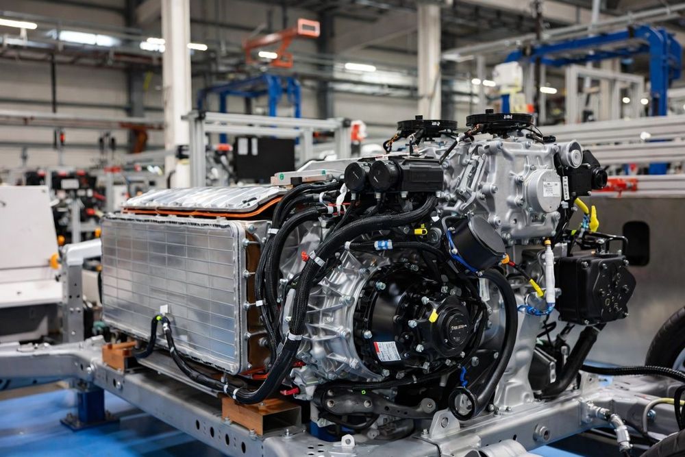
The High-Voltage Shift in Electric Powertrains
The transition from internal combustion engines (ICE) to hybrid and battery electric vehicles (BEVs) fundamentally alters the electrical parameters of automotive connector design. While traditional vehicles operate on 12 VDC or 24 VDC low-voltage architectures, modern EV powertrains operate at high voltages ranging from 400 VDC up to 800 VDC (and expanding toward 1000 VDC for ultra-fast charging systems).
At these voltage and current levels, electrical arcing, severe thermal dissipation, electromagnetic radiation, and human shock hazards present critical safety risks. Connectors serving EV traction batteries, inverters, onboard chargers (OBC), and DC-DC converters must adhere to specialized high-voltage safety standards.
Critical Engineering Constraints for EV Connectors
Designing high-voltage EV interconnects requires addressing distinct physical safety and electrical transmission challenges:
1. High-Voltage Interlock Loop (HVIL) Integration
Safety Function: An HVIL is a low-voltage circuit loop built directly into a high-voltage connector assembly. The HVIL pin contacts are engineered with a shorter physical length than the main high-voltage power pins.
Operational Sequence: During disconnect, the shorter HVIL pins break contact before the main high-voltage power pins separate. This instant disconnection signals the inverter or battery management system (BMS) controller to shut off power flow via high-voltage contactors within milliseconds, preventing lethal DC electrical arcing across the opening power contacts.
2. Touch-Proof Finger Safety (IP2XB / IEC 60529)
Safety Requirement: EV high-voltage connectors must be physically touch-proof on both mated and unmated plugs to protect factory technicians and emergency responders.
Execution: Connectors must meet IP2XB standards, using plastic shrouds and insulated internal pin tips that prevent a standard jointed test finger (12mm diameter) from touching any live conductive surface.
3. Extended Creepage and Clearance Distances
To prevent electrical tracking (surface breakdown) and dielectric air breakdown under 800V operating conditions:
Clearance Distance: The shortest distance through air between two conductive parts must be expanded significantly compared to low-voltage connectors.
Creepage Distance: The shortest distance along the surface of the insulating plastic housing must account for potential surface contamination, requiring high Comparative Tracking Index (CTI) engineering plastics (typically CTI Class 1, greater than 600V).
4. Thermal Management and Continuous High Current
Fast-charging systems push continuous currents exceeding 300A to 500A through power connectors.
Contact Resistance Control: Internal contacts utilize silver-plated or gold-plated copper alloy crown springs (such as LouverTac or RADSOK geometry) to maintain multi-point contact surface area and keep contact resistance below micro-ohm levels.
Integrated Temperature Sensing: High-power EV connectors often integrate dedicated PTC thermistors or NTC temperature sensors directly adjacent to the power terminals to monitor real-time thermal rise and trigger current derating before housing melting occurs.
Key EV Connector Standards to Follow
When specifying or designing EV high-voltage connector systems:
- ISO 6469-3 / ECE R100: International safety standards defining electrical safety, insulation resistance, and protection against direct and indirect contact in electric road vehicles.
- SAE J1772 / IEC 62196: Global conductive charging standards governing AC and DC fast-charging inlet interfaces (CCS Combo 1, CCS Combo 2, and NACS/SAE J3400).
- USCAR-37: Performance specification for high-voltage automotive electrical connector systems (60V to 600VDC).