Defining Pitch in Electronics
In the realm of electronics and interconnect design, pitch refers to the center-to-center distance between adjacent electrical contacts or pins within a single row. It is a critical spatial dimension that must be precisely matched between mating halves, printed circuit board footprints, and automated assembly machinery.
When measuring pitch, engineers do not measure the gap between the edges of the pins; instead, they measure from the absolute center line of one pin to the absolute center line of the next. This ensures that the measurement remains independent of variations in individual pin widths or manufacturing tolerances.
Standard vs. Fine Pitch Classifications
As consumer electronics have shrunk, the spacing between pins has continuously compressed. Pitch is broadly categorized into two families:
Legacy and Standard Pitch (2.54mm and larger)
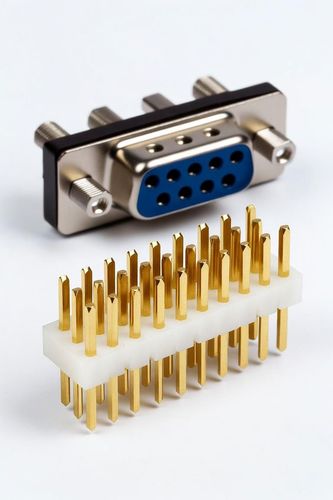
- 2.54mm (0.100 inches): The traditional standard for electronics prototyping. It matches breadboard spacing, standard IDC ribbon cables, and traditional pin headers. It is easy to work with by hand and robust against minor alignment errors.
- 3.96mm / 5.08mm: Larger pitches used in heavy-duty power supplies, terminal blocks, and industrial machinery where thick wires must be handled safely.
Fine and Ultra-Fine Pitch (Below 2.0mm)
- 2.0mm and 1.27mm: Mid-tier sizes popular for space-constrained internal board connections in consumer electronics.
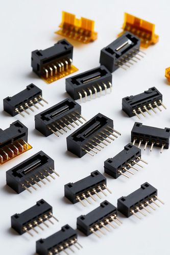
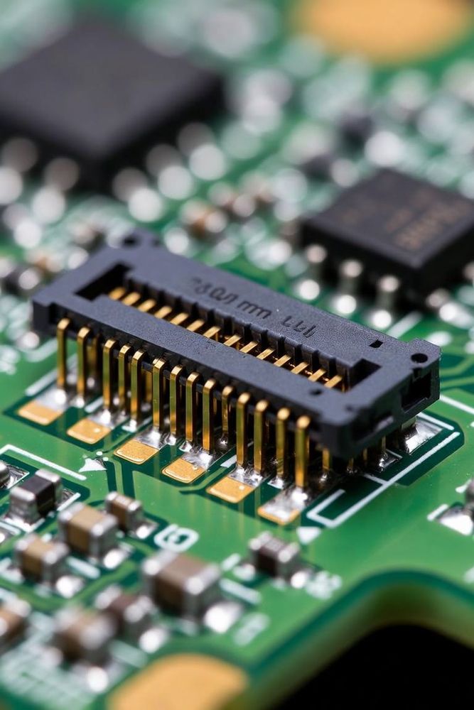
- 1.0mm down to 0.3mm: Categorized as fine or ultra-fine pitch. These micro-dimensions are standard in Flexible Printed Circuit (FPC) and Flat Flexible Cable (FFC) connectors used to link displays, camera modules, and batteries to main logic boards in ultra-thin devices like smartphones and laptops.
Critical Engineering Trade-offs of Small Pitch
Choosing the right pitch is a constant exercise in managing trade-offs between physical size, electrical capability, and manufacturing difficulty.
1. Spatial Density vs. Current Capacity
The closer contacts are placed to one another, the less copper material can be allocated to each individual pin. Consequently, fine-pitch connectors have much lower current-carrying capacities. While a large 5.08mm pitch terminal block can easily handle 15 Amps of current, an ultra-fine 0.4mm pitch FPC connector might only handle 0.3 Amps per pin.
2. Voltage Thresholds and Isolation
As the distance between pins shrinks, the physical gap of air or plastic separating them decreases. This lowers the dielectric breakdown threshold, making fine-pitch connectors susceptible to electrical arcing or short-circuiting at lower voltages, especially in humid or dusty environments.
3. Manufacturing Tolerances and Defect Rates
Soldering a 2.54mm pitch header to a board can be done easily by hand with a basic soldering iron. Soldering a 0.4mm surface-mount connector requires advanced automated pick-and-place machinery, high-resolution optical inspection systems, and precise solder paste stencil tolerances. A minor shift during automated assembly on a fine-pitch component can cause solder bridging, creating shorts across adjacent pins.