Toolless RF Coupling
While the threaded coupling of an SMA connector provides unmatched mechanical stability for stationary RF systems, the manual installation overhead becomes a distinct drawback in rapid manufacturing environments or tight spatial enclosures. When an application demands quick, toolless servicing paired with a highly compact footprint, hardware engineers step away from threaded form factors to utilize Subminiature Version B (SMB) connectors. Operating at an optimal frequency range up to 4 GHz, SMB interfaces trade heavy torque locking for a high-efficiency snap-on coupling mechanism.
Spring-Finger Snap-On Latch Mechanics
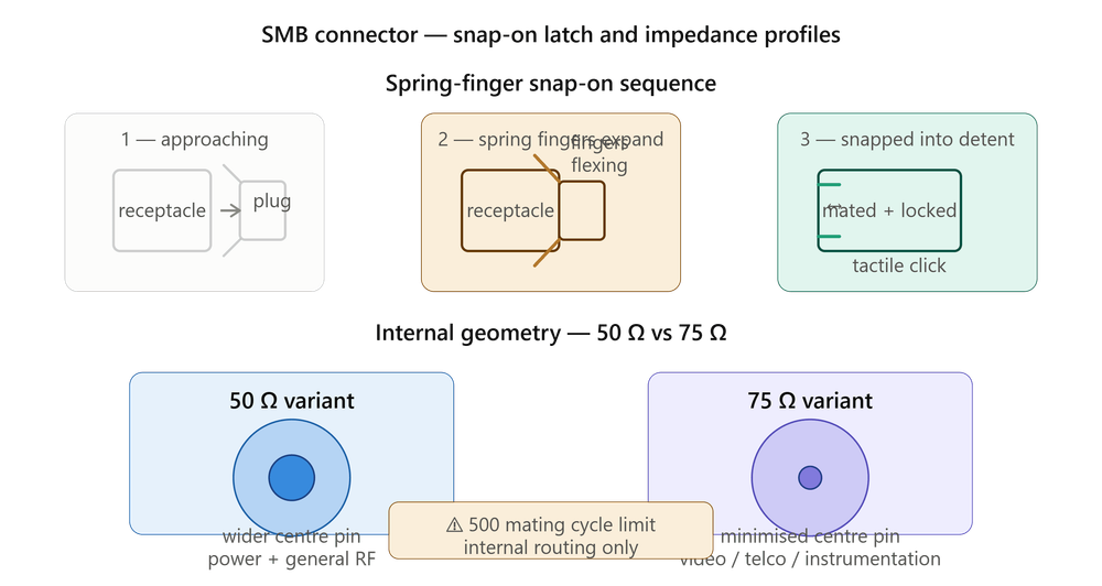
The core engineering innovation of the SMB connector is its spring-finger snap-on latch mechanism. The outer interface of the plug features a compliant, slotted spring-metal sleeve that expands outwardly as it slides over the receptacle's chamfered entry skirt. Once fully seated, the sleeve snaps firmly into a machined detent groove on the receptacle body, providing a distinct tactile click that confirms a positive lock. This click ensures that the internal pin-and-socket contacts are perfectly mated along their electrical datum planes without requiring calibrated torque wrenches or manual spinning, slashing factory routing time and enabling rapid blind-mating inside dense enclosures.
50 Ohm vs. 75 Ohm Configurations
Electrically, SMB connectors are manufactured in two distinct internal configurations to match specific signal archetypes:
- 50 Ohm Variant: The industry standard for general wireless signal routing, utilizing robust internal pin profiles optimized to maximize power transmission efficiency.
- 75 Ohm Variant: Shifts the internal conductor-to-shield diameter ratio and utilizes a minimized center pin to drastically reduce signal attenuation. The preferred choice for high-precision video distribution, telecommunications switching systems, and digital instrumentation lines.
Regardless of impedance, the snap-on interface introduces a slight performance trade-off: because the housing can rotate freely within its detent groove, the connection is more prone to minor signal reflections if subjected to heavy lateral cable tugging compared to a rigid, threaded SMA link.
Mating Cycle Limits and Layout Considerations
The mechanical footprint of the SMB interface is optimized for high-density circuit board layouts — roughly one-third smaller than standard SMA packages, making them highly compatible with low-profile right-angle SMT mounts and vertical blind-mate plug-in card configurations.
However, layout designers must account for the mechanical retention profile of the snap-on interface. Because the coupling relies entirely on the spring tension of the metal sleeve, repetitive mating cycles will slowly fatigue the fingers, reducing the engagement force. SMB systems are typically rated for a total lifespan of 500 mating cycles, requiring engineers to isolate these ports from external user-accessible maintenance panels and reserve them for protected, internal system routing blocks.
Speed vs. Security
SMB connectors deliver the ideal balance of compact RF performance and assembly speed for internal board routing and shielded module applications. By understanding their frequency ceiling, impedance options, and mating cycle limits, engineers can deploy SMB interfaces with confidence in the right system contexts.