The Free-Hanging Challenge
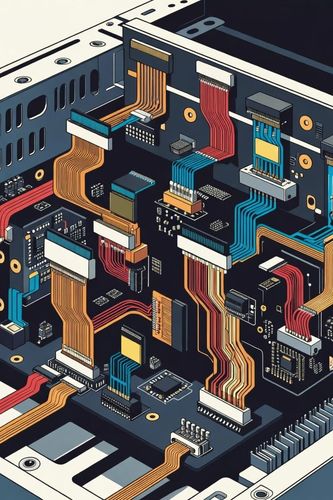
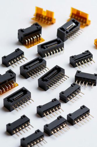
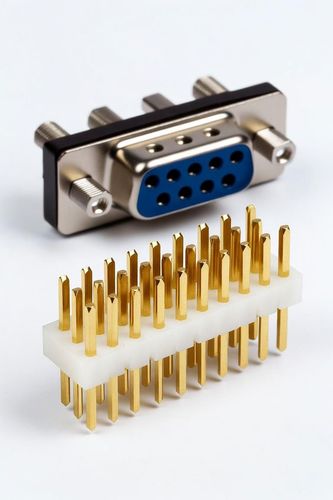
Unlike board-mounted interfaces that benefit from the rigid structural backing of a PCB substrate, inline wire-to-wire connectors operate in a free-hanging state. These components are spliced straight into the middle of a wiring harness to link independent cable sub-assemblies. Because they float freely within a system enclosure, inline connectors face unique mechanical challenges. They must bear continuous tensile pulling forces, resist severe torsional twisting, and maintain absolute electrical continuity while being bounced against structural frames.
Cable Tension and Strain Relief
The primary vulnerability of an inline connection is cable tension. When an operator pulls on a wiring harness during installation or routing, that mechanical force travels down the wire and pulls directly on the crimp contact inside the housing. If the housing lacks proper strain relief, this tension will eventually pull the terminal completely out of its locking cavity.
To prevent terminal back-outs, high-performance inline housings feature elongated backshells or integrated cable tie tracks. These features clamp the outer insulation jackets of the wire bundle together, ensuring that any external pulling force is absorbed entirely by the rugged plastic shell rather than the fragile copper crimp joints inside.
Positive Locking in a Free-Floating State
Mating security in a free-floating state demands robust, positive mechanical locking. Simple friction-fit connectors are unusable for inline deployment because standard cable movement can pull them apart over time. Inline housings utilize integrated, pivoting thumb latches or sliding locks that provide both a sharp audible and tactile click when fully engaged. To protect the connection from accidental release if the harness catches on a sharp metal edge during routing, these latches are shrouded by protective plastic wings.
Blind-Panel Routing and Scoop Prevention
Inline systems must handle the challenge of blind panel routing. When a technician is reaching deep behind a dashboard or inside an industrial enclosure, they often cannot see the mating interface and must rely entirely on touch. Inline connector housings are engineered with heavy geometric polarization, featuring asymmetric shapes, distinct chamfers, and internal guide keys that make it physically impossible to force the plug in upside down or backward.
Additionally, many inline housings utilize extended guiding skirts that align the outer shells before the internal pins ever make contact. This prevents "scooping"—a devastating failure mode where angled insertion causes a male pin to strike the face of a female terminal, bending or breaking the metal before it can slide into place.
Mechanical Completeness in Free-Hanging Systems
Inline wire-to-wire connectors provide the essential modularity needed to break massive electrical networks down into manageable, field-serviceable wire harnesses. Achieving long-term field survival requires specifying housings with integrated cable strain reliefs, positive locking mechanisms that resist accidental unlatching, and robust geometric polarization. When these mechanical features are fully integrated, inline joints maintain clean, low-resistance connections even when floating in the most chaotic mechanical environments.