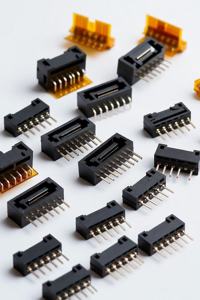
At 5Gbps and above, a flexible printed circuit connector stops being a purely mechanical component and becomes, functionally, a radio-frequency part. That shift catches designers off guard more often than it should: 4K/120Hz and 8K/60Hz video, now standard across laptops, tablets, and medical imaging displays, pushes enough data through a flex cable that a 0.5mm pitch connector specified without RF discipline becomes a direct source of EMI and signal degradation, not a neutral mechanical junction.
Impedance: Why 85Ω Is Replacing the 100Ω Legacy Standard
Impedance discontinuity is the single biggest threat to signal integrity at these speeds. 100Ω has been the long-standing legacy target for differential pairs, but many current protocols — PCIe-based interfaces prominent among them — are shifting to an 85Ω target instead. Mismatch between the connector's actual impedance and the system's target creates what's effectively a "bump" in the transmission line: a point of reflected energy that shows up as jitter on the receiving end, and at 10Gbps, a reflection large enough can cause outright link failure rather than just a degraded margin.
The practical fix is specifying connectors that come with genuine high-speed credentials, not just a tight pitch. Look specifically for parts whose datasheet includes a Time Domain Reflectometry (TDR) plot — this is the direct evidence that the manufacturer has tuned the terminal geometry to hold a flat 85Ω or 100Ω impedance all the way through the mating interface, rather than just publishing a pitch dimension and leaving impedance unverified.
Shielding: Treating the Cable as a Faraday Cage, Not Just a Wire
At 5Gbps and above, an unshielded FPC cable functions as an unintentional broadcast antenna — which is a real problem both for signal integrity and for FCC/CE certification. Three things separate a connector genuinely built for this from one that just happens to have a metal shell:
Full metal shells that completely enclose the plastic housing and make continuous wiping contact with the FPC's own silver or copper shield layer, rather than a shell that only partially covers the housing.
Multiple SMT grounding tabs connecting the shell directly into the PCB's internal ground plane — a single ground tab is rarely sufficient once you're pushing multi-gigabit rates through a 0.3mm-0.5mm pitch.
A G-S-S-G (Ground-Signal-Signal-Ground) pinout on tight-pitch designs specifically. At 0.3mm pitch, adjacent pins sit close enough that crosstalk between them is the default outcome, not an edge case — the G-S-S-G pattern exists specifically to isolate each differential pair from its neighbors, which is what keeps a high-resolution video signal from degrading into visible noise on the display.
Where This Overlaps With Board-Level High-Speed Design
The same 85Ω-versus-100Ω impedance discipline and reflection-avoidance logic that governs FPC connector selection also governs board-to-board and mezzanine connector selection at similar data rates — the physics doesn't change just because the form factor does. Our guide to ultra-low profile PCIe Gen 7 connectors covers the same impedance-tolerance and signal-reflection problem in a rigid board-to-board context, and is a useful companion read if your design mixes both flex-cable and board-to-board high-speed interfaces in the same system.