Video Bandwidth at Microwave Scale
Driving modern high-resolution displays requires routing massive streams of uncompressed digital data in real time. The HDMI 2.1 specification supports bandwidths up to 48 Gbps using Fixed Rate Link (FRL) technology, while the DisplayPort 2.1 standard pushes capacity even further to 80 Gbps via Ultra High Bit Rate (UHBR20) signaling. At these microwave-scale frequencies, the physical connectors on the graphics card and the display panel can no longer behave as passive plastic clips. The internal lead-frames, contact spring interfaces, and PCB breakout regions must be engineered with meticulous precision to prevent impedance drops and severe signal phase jitter from corrupting the high-definition pixel array.
Differential Impedance Control
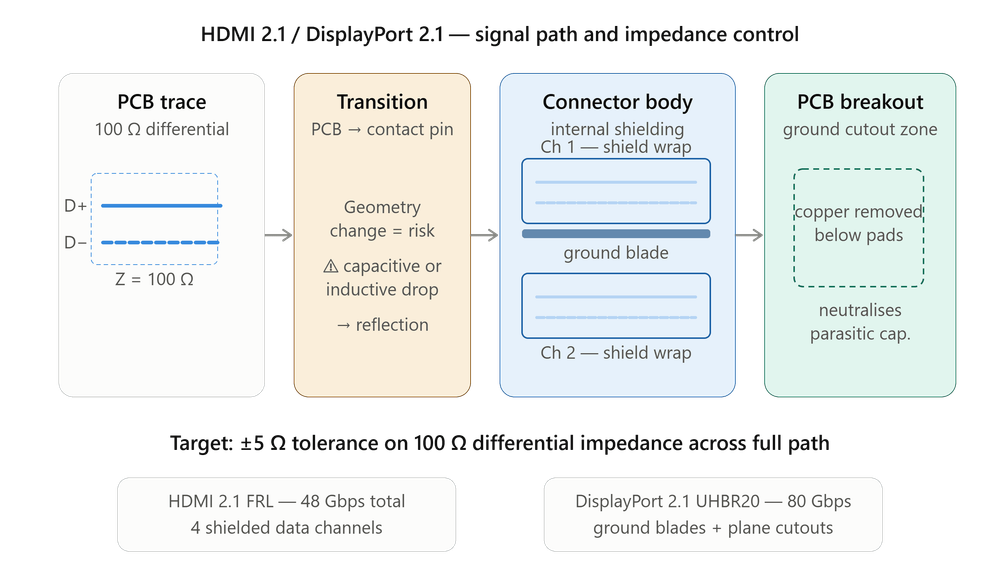
The fundamental engineering challenge in both HDMI and DisplayPort connectors is maintaining a strict, uniform differential impedance profile across the entire mechanical junction. The target standard is tightly bounded at 100 Ohm (or 85 Ohm for specific system designs), with an allowable tolerance of just ±5 Ohm. When a high-speed differential signal transitions from a flat PCB trace into the vertical stamped metal spring contacts of an HDMI or DisplayPort receptacle, it encounters a localized geometric change. If this transition isn't carefully managed, it creates a capacitive or inductive drop that reflects a portion of the signal energy back to the source, closing the signal eye and triggering pixel dropouts or complete link failures.
Internal Channel Isolation
To combat these reflections, high-bandwidth video connectors deploy extensive physical isolation tactics. In an HDMI 2.1 layout, each of the four high-speed data channels is isolated within its own dedicated, wrapped metallic shield compartment inside the connector body, directly paired with a local ground return pin. DisplayPort 2.1 connectors utilize a similar high-density layout where internal ground blades run parallel to the signal pins, minimizing the loop inductance of the return path.
Furthermore, the PCB breakout region directly beneath these SMT pads implements advanced ground plane cutouts, removing the copper layer immediately below the surface pads to neutralize the parasitic capacitance generated by the wide metal footprint of the connector feet.
Intra-Pair Skew Compensation
Another critical distortion mechanism that video connector engineers must mitigate is intra-pair skew. At the frequencies required to drive 8K and 16K displays at high refresh rates, the positive and negative sides of a differential pair must remain perfectly synchronized down to the picosecond level. Because DisplayPort and HDMI connectors feature asymmetrical physical configurations—where the outer rows of pins have slightly different lengths than the inner rows—the internal lead-frames must be dynamically compensated.
Manufacturers alter the thickness and path routing of individual metal contacts inside the plastic housing, ensuring that the electrical length of both paths remains completely identical. This eliminates phase misalignment, prevents differential-to-common mode signal conversion, and keeps electromagnetic emissions safely within regulatory bounds.
Microwave-Grade Precision for the Living Room
High-bandwidth display interfaces act as the primary pipelines for high-resolution visual rendering. Successfully specifying and layout-routing these connectors requires minimizing geometric impedance mismatches at the vertical solder transition, optimizing ground plane voids to eliminate parasitic capacitance, and ensuring absolute electrical path uniformity to eliminate intra-pair skew. When these measures are fully integrated, HDMI and DisplayPort interfaces provide rock-solid, error-free pixel delivery across high-performance display systems.