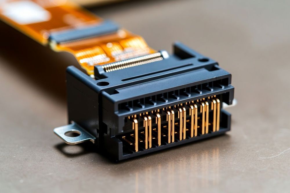
The High-Density Trade-Off in FPC Connector Pitch
In compact hardware design, connector pitch—the center-to-center distance between adjacent conductive pins—dictates both the physical footprint of the connector and the routing density of the flexible printed circuit (FPC). As consumer, medical, and wearable electronics demand higher pin counts in smaller enclosures, FPC connector pitches have shrunk from standard 1.0mm and 0.5mm sizes down to ultra-fine 0.4mm, 0.3mm, and even 0.2mm geometries.
However, selecting an ultra-fine pitch FPC connector introduces significant engineering trade-offs in manufacturing yields, PCB fabrication costs, mechanical durability, and electrical current carrying capacity.
Engineering Analysis by Pitch Class
Evaluating pitch options requires balancing board space savings against assembly and electrical constraints.
0.5mm Pitch: The Industry Standard for Versatility
- Target Applications: Mainboard-to-display modules, internal sub-assembly jumpers, industrial controls, and automotive infotainment systems.
- Manufacturability: Excellent SMT assembly yields using standard stencil printing tolerances and conventional Surface Mount Technology (SMT) pick-and-place equipment.
- Current Capacity: Typically handles 0.5A to 1.0A per contact, making it suitable for combining low-power rails alongside control signals.
- Trace Breakout: Allows standard PCB trace widths and clearances (0.10mm line/space) without requiring High-Density Interconnect (HDI) microvia stackups.
0.4mm Pitch: The Sweet Spot for High-Density Mobile Devices
- Target Applications: Smartphones, smartwatches, compact camera modules, and portable medical diagnostics.
- Manufacturability: Requires tight control over SMT stencil design (laser-cut apertures with electropolishing) to prevent solder bridging between adjacent pins.
- Current Capacity: Typically rated for 0.3A to 0.5A per contact, requiring multiple parallel pins for power distribution rails.
- Trace Breakout: Operates on the boundary between standard PCB layout rules and HDI requirements, often necessitating fine-line trace geometries (0.075mm line/space).
0.3mm (and 0.2mm) Pitch: Ultra-Fine Pitch for Space-Constrained Hardware
- Target Applications: Advanced wearables, AR/VR smart glasses, hearing aids, and ultra-compact sensor probes.
- Manufacturability: High susceptibility to solder bridging, pin misalignment, and stiffener registration errors during automated assembly. Requires precise optical alignment systems on SMT lines.
- Current Capacity: Limited to 0.2A to 0.3A per contact. Power rails must be distributed across multiple dedicated contacts.
- Trace Breakout: Demands HDI PCB fabrication with microvias-in-pad and advanced fine-line etching (0.05mm line/space on the FPC substrate), significantly increasing circuit fabrication costs.
Key Design Factors When Selecting Pitch
When choosing the optimum FPC pitch for your circuit layout:
- Factor in PCB Assembly Yields: While a 0.3mm pitch connector saves critical board area, the tighter SMT process window increases the risk of solder bridging and rework costs. Choose 0.5mm or 0.4mm pitch unless mechanical space constraints strictly mandate a 0.3mm interface.
- Calculate Power Rail Allocation: If your FPC carries system power rails (e.g., 5V display backlight power at 1.5A), a 0.3mm connector requires 5 to 8 parallel contacts solely for power and ground, offsetting much of the space saved by choosing a finer pitch.
- Account for Stiffener Alignment Tolerances: As connector pitch drops below 0.4mm, the mechanical tolerance of the FPC polyimide stiffener alignment becomes critical. Slight shifts in stiffener lamination cause cable pad misalignment relative to the connector's internal spring contacts.