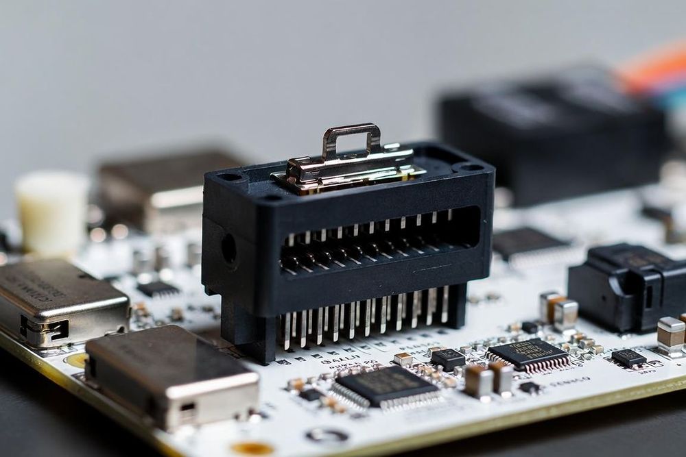
What is Connector Pitch and Why Does It Matter?
In electronic interconnect design, pitch is defined as the center-to-center distance between adjacent conductive pins or terminals. Expressed in millimeters (or inches for legacy hardware, like 0.1-inch / 2.54mm pitch headers), pitch dictates the physical density of the connector footprint on your printed circuit board.
As products shrink and functionality demands grow, hardware designers are forced to transition from standard pitches down to fine and ultra-fine pitches. However, reducing connector pitch is never a free lunch: every step down in pitch forces tighter PCB fabrication tolerances, compromises individual pin current capacity, and drastically narrows your mechanical mating alignment margins.
Comparing Key Pitch Classifications
To understand the practical layout implications, let's examine three of the most widely used fine-pitch classifications in modern hardware design: 0.4mm, 0.5mm, and 1.0mm.
0.4mm Pitch: Ultra-Fine Density for Space-Constrained Designs
The 0.4mm pitch classification is the standard for modern smartphones, smartwatches, high-end wearables, and compact camera modules.
- Typical Applications: Board-to-board mezzanine stackups and fine-pitch FPC flex connectors in mobile electronics.
- Current Capacity: Extremely limited, generally carrying around 0.3A to 0.5A per pin. High-power rails require ganging multiple adjacent pins together.
- PCB Trace Routing & Fanout: Requires microvias, thin traces (typically 3 mil / 0.075mm width and space), and high-density interconnect (HDI) PCB fabrication stacks.
- Assembly Considerations: High risk of solder bridging during reflow. Stencil thickness must be carefully controlled (often 80 to 100 microns) with laser-cut step-down stencils.
0.5mm Pitch: The Sweet Spot for High-Density Embedded Hardware
The 0.5mm pitch strikes an optimal balance between high contact density and standard, cost-effective PCB manufacturing rules.
- Typical Applications: Single-board computers (SBCs), display interfaces (eDP, LVDS), high-pin-count FPC connectors, and compact robotics controllers.
- Current Capacity: Moderate, typically rated between 0.5A and 1.0A per contact.
- PCB Trace Routing & Fanout: Can usually be routed out on standard 4-layer or 6-layer boards using standard 4-mil or 5-mil trace/space rules, avoiding expensive HDI microvia surcharges.
- Assembly Considerations: Much broader SMT process window than 0.4mm pitch. Standard pick-and-place machinery easily handles alignment without requiring ultra-high-end optical vision upgrades.
1.0mm Pitch: Rugged, Higher-Power Compact Interfaces
The 1.0mm pitch serves as the bridge between compact signal connectors and larger power/industrial interconnects.
- Typical Applications: Industrial IoT gateways, automotive sensor modules, drone flight controllers, and rugged wire-to-board power interfaces.
- Current Capacity: Substantially higher, routinely handling 1.5A to 3.0A per pin depending on contact material and copper mass.
- PCB Trace Routing & Fanout: Extremely forgiving layout rules. Allows wide copper traces to route directly between pads on standard 2-layer or 4-layer boards with standard 1-ounce or 2-ounce copper weights.
- Assembly Considerations: High SMT assembly yields, excellent visual solder inspection capability, and high mechanical tolerance against board twisting and enclosure flex.
Engineering Trade-Offs When Selecting Pitch
When deciding between fine pitches like 0.4mm/0.5mm and standard pitches like 1.0mm or larger, evaluate these critical design vectors:
1. Thermal Management and Current Delivery
Finely pitched contacts have smaller cross-sectional metal areas and tight pin-to-pin spacing, which traps heat inside the plastic insulator. If your design requires delivering 5V at 3A to a display or processing module, a 0.4mm pitch connector will require 6 to 10 dedicated power pins working in parallel to avoid localized overheating. A 1.0mm pitch connector might handle that same current load across just two pins.
2. PCB Fabrication Cost (Standard vs. HDI)
Designing with 0.4mm pitch connectors often forces your PCB vendor into High-Density Interconnect (HDI) manufacturing, requiring laser-drilled blind/buried microvias and tight impedance control tolerances. This can increase bare-board fabrication costs significantly. If enclosure space permits, stepping up to a 0.5mm or 1.0mm pitch can keep your board within standard low-cost fabrication capabilities.
3. Mechanical Tolerance Stack-Up and Alignment
Smaller pitch connectors have smaller mating entry funnels and lower tolerance for blind mating. In multi-board assemblies, tiny manufacturing variations in housing alignment can cause pin stubbing or cracked solder joints on fine-pitch connectors. If your product requires field assembly by hand, a larger 1.0mm pitch provides crucial mechanical robustness and tactile feedback.