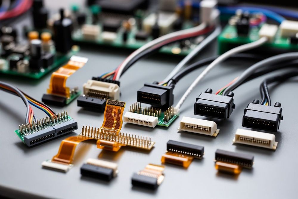
Introduction to Electrical Interconnect Families
Every hardware project, from a simple sensor node to a complex industrial controller, relies on electrical connectors to join subsystems together. For junior hardware engineers and PCB designers, navigating the vast array of available interconnect options can feel overwhelming. Connectors do not merely bridge circuits electrically; they act as mechanical anchors that dictate board enclosure layout, thermal management, and manufacturability.
At the highest functional level, electronic connectors are grouped by how they connect within an assembly: bridging circuit boards directly, linking flexible wire harnesses to boards, or joining cables together in mid-air.
The Core Interconnect Architecture Categories
Understanding how these families differ structurally helps you select the right form factor early in schematic capture and floorplanning.
Board-to-Board (B2B) Connectors
Board-to-board connectors link two printed circuit boards directly without intervention from wire leads. They are ideal for high-density architectures, system-on-module (SoM) setups, and daughter-card stackups.
- Mezzanine / Parallel: Boards stack parallel to each other. The critical dimension is stack height.
- Right-Angle / Perpendicular: Boards meet at a 90-degree angle, typically seen in backplane and chassis expansion slots.
- Coplanar / Edge-to-Edge: Boards lie flat on the same plane, frequently used for modular LED assemblies or continuous sensor strips.
Wire-to-Board (W2B) Connectors
Wire-to-board connectors bridge flexible discrete wires or cable looms directly to a rigid PCB. They are common for bringing power, off-board switches, displays, and internal peripheral sensors onto the main circuit.
- Headers: The rigid male or female array soldered to the board surface or through holes.
- Housings and Crimp Terminals: The cable-side plastic plug that retains individual wire contacts that have been mechanically crimped onto conductor strands.
Wire-to-Wire (W2W) Connectors
Wire-to-wire connectors join two cable assemblies in mid-air or pass through a chassis wall. They enable modular harness manufacturing, allowing large machines or vehicle architectures to be split into manageable wiring looms for easier installation and field maintenance.
- Free-Hanging: Suspended inside a cable sleeve or conduit.
- Panel Mount: Clamped or screwed into an enclosure cutout to form a sealed bulkhead pass-through.
Flexible Flat Cable (FFC) and Flexible Printed Circuit (FPC) Connectors
When internal enclosure space is severely constrained—such as in smartphones, cameras, and wearable devices—traditional discrete wire harnesses are too bulky. FFC/FPC connectors clamp onto thin, ribbon-like flexible circuits. They utilize Zero Insertion Force (ZIF) or Non-ZIF locking actuators to secure ultra-fine pitch contacts in tight spaces.
Physical Termination and Mounting Options
Once you select an interconnect category, you must decide how the connector physically attaches to your PCB.
Surface Mount Technology (SMT)
SMT connectors sit flat on copper solder pads on the outer board layer. They offer maximum route-through space on inner PCB layers and support high-density pick-and-place automation. However, SMT leads provide weaker mechanical shear strength compared to through-hole pins under physical stress.
Through-Hole Technology (THT)
THT connectors extend metallic leads entirely through drilled PCB vias, soldered on the opposite side. They offer vastly superior mechanical anchor strength, making them ideal for heavy power inputs, user-facing ports (like USB or barrel jacks), and high-vibration environments.
Press-Fit / Compliant Pin
Common in server backplanes and telecommunications infrastructure, press-fit contacts use compliant metallic pins driven mechanically into plated through-holes. This creates a solderless, gas-tight joint, avoiding thermal stresses caused by reflow soldering on thick multi-layer boards.
Key Design Factors When Selecting a Category
When choosing between these primary families during early hardware scoping, balance the following trade-offs:
- Signal Density vs. Current Capacity: Finer pitch connectors (like 0.4mm B2B or FPC) pack dozens of signals into millimeters of space but carry very little current per pin (typically 0.3A to 0.5A). Power applications require larger pitch headers (like 3.96mm or 5.08mm) with heavy contacts capable of handling 10A or more.
- Mechanical Stress and Strain Relief: Cable assemblies wiggle and pull under vibration. Wire-to-board and wire-to-wire systems must incorporate latching mechanisms and strain relief, whereas board-to-board connectors require rigid enclosure alignment to prevent solder joint shear.
- Assembly Complexity: Crimp-and-poke wire terminals require specialized crimp dies and harness assembly steps, whereas FPC flex cables simplify routing but require delicate hand assembly or specialized automated placement.