Introduction: The Human Factor in Systems Assembly
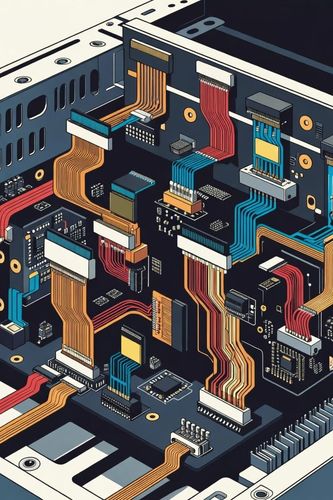
Modern electronic architectures feature dense control panels, complex wiring harnesses, and packed PCBs where dozens of identical or structurally similar connectors sit immediately adjacent to one another. During high-velocity factory manufacturing, or stressful field servicing under poor lighting, the risk of a technician plugging a cable into the wrong receptacle is high.
Mis-mating can be catastrophic. Connecting a high-voltage power line to a low-voltage differential data line will instantaneously fry sensitive silicon components. To systematically eliminate this failure mode, engineers utilize polarization and keying systems—mechanical and visual features that ensure a connector can only be mated to its designated counterpart, in its correct orientation.
Part 1: Polarization vs. Keying — Clearing the Ambiguity
While often used interchangeably in casual conversation, polarization and keying refer to two distinct engineering implementations of error-proofing (Poka-Yoke).
Polarization
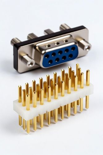
Polarization describes a connector housing designed with an asymmetric shape that permits mating in only one specific orientation. A classic example is the D-Subminiature profile or a standard USB port. The housing geometry ensures that the user cannot plug the connector upside down or sideways. Polarization focuses purely on orientation accuracy for a single mated pair.
Keying
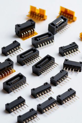
Keying goes a step further by differentiating between multiple structurally identical connector pairs. Keying relies on modifying specific geometric features—such as adding unique slots, ribs, tabs, or pins—so that a specific male plug can only insert into one specific female receptacle, even if there are five other identical-looking connectors right next to it.
Part 2: Implementation Methodologies in Engineering
1. Geometric Shrouding and Ribbing
The most robust and common form of keying is integrated straight into the injection-molded housing shell. Connectors are designed with unique internal guiding rails or external keys that must perfectly align before the internal electrical contacts can make physical contact.
For high-density circular connectors (such as MIL-DTL-38999 series), this is accomplished by rotating the master keyway location relative to a set baseline (e.g., Normal, A, B, C, D, N positions), allowing the same shell size and pin layout to be used safely multiple times on the same bulkhead.
2. Pin-Out Configuration Manipulation
In applications where designing custom-molded plastic shells is cost-prohibitive, engineers can achieve keying by selectively removing pins from the male header and plugging the corresponding holes in the female receptacle using dummy plastic keys. If a technician attempts to mis-mate the cable, a solid pin will strike a blocked hole, physically halting the insertion before electrical contact is made.
3. Visual and Color-Coded Separation
While mechanical barriers provide physical blocking, visual coding serves as the first line of cognitive defense for the operator. Industrial and automotive standards (such as USCAR or FAKRA RF connectors) tie specific mechanical keying geometries to highly distinct, standardized color schemes (e.g., Jet Black for Key A, Cream White for Key B, Light Blue for Key C). This dual-layer approach—visual identification backed by mechanical enforcement—dramatically speeds up assembly velocity on production floors.
Part 3: Advanced Challenges — Scoop Proofing and Mechanical Robustness
Blind Mating
When connectors must be mated in hard-to-reach spaces where the technician cannot physically see the interface (such as the backplane of a server rack), the keying system must support blind mating. This requires wide, chamfered entry funnels that capture a misaligned connector plug and gently guide it into correct rotational alignment before the keying mechanisms engage.
Scoop Proof Design
A critical design pitfall occurs when a connector's shell allows the male pins to slide sideways across the face of the receptacle during an angled mating attempt. This action can bend or break delicate pins—a failure known as "scooping."
High-reliability connectors are engineered to be scoop-proof, meaning the outer protective shell extends far past the tips of the internal pins. The keying alignment occurs entirely within the protective shroud before the electrical contacts can physically touch.
Conclusion: Designing Out Human Error
Reliable system design acknowledges that human installation error is an inevitability if left unchecked. Relying on assembly manuals or simple operator attentiveness is an architectural vulnerability. By integrating robust polarization to enforce correct orientation, configuring distinct geometric keying positions to prevent cross-routing, and utilizing scoop-proof shrouds, connector engineers ensure that physical hardware inherently blocks assembly errors, protecting sensitive systems from catastrophic electrical faults.