Mechanical Vulnerability at the Rigid-to-Flex Transition Zone
Flexible Printed Circuits (FPC) provide exceptional dynamic bend performance, but they are vulnerable to tearing where flexible polyimide meets rigid components. The point where a flexible cable enters an SMT connector housing or joins a rigid PCB section creates a localized stress concentration zone.
When an external force pulls or twists the flex cable, stress concentrates precisely along the rigid-to-flex boundary line. Without mechanical strain relief, this stress causes copper traces to crack, tears polyimide base films, or peels SMT connector pads directly off the PCB. Protecting flex assemblies requires integrating stiffeners, strain relief features, and mechanical anchor points into the physical design.
Selecting FPC Stiffeners: Polyimide, FR4, and Stainless Steel
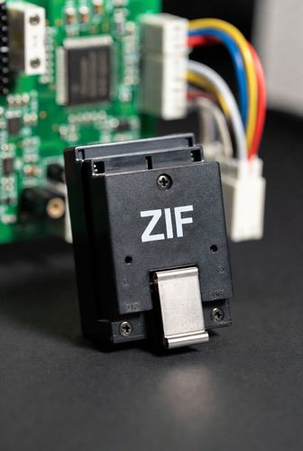
Because flexible polyimide substrates are too thin (25 μm to 50 μm) to engage properly inside ZIF connectors or withstand SMT reflow forces, engineers add stiffeners to the back of flex tail contacts. Stiffeners add mechanical rigidity without compromising the flexibility of the remaining cable.
Common stiffener materials include:
- Polyimide (PI) Stiffeners: Thin polyimide sheets (0.05 mm to 0.2 mm) bonded to the back of FPC contact tails using pressure-sensitive or thermally cured acrylic adhesives. PI stiffeners adjust total tail thickness to match ZIF connector cavity specifications (0.20 mm or 0.30 mm).
- FR4 Glass-Epoxy Stiffeners: Rigid FR4 boards (0.2 mm to 1.6 mm) laminated to the underside of flex zones mounted with heavy surface-mount components (connectors, ICs, passives). FR4 prevents the flex substrate from bowing during SMT reflow and component placement.
- Stainless Steel / Aluminum Stiffeners: Metal plates bonded to flex circuits in ultra-compact designs requiring high rigidity, thin profiles, or grounded heat dissipation pathways.
Design Rules for Stiffener Transition Zones
Improperly designed stiffener edges can create sharp stress points that accelerate tearing. Follow these key layout rules when specifying stiffeners:
- Overlap Coverlays and Stiffeners: Always overlap the polyimide coverlay over the leading edge of the stiffener by at least 0.5 mm. Never align the stiffener edge directly with a coverlay termination line, as this forms a single failure point across all copper traces.
- Smooth Stiffener Corners: Specify rounded corners (minimum 0.5 mm radius) on all stiffener outlines to prevent sharp corners from piercing adjacent polyimide films.
- Extend Stiffeners Past Component Footprints: Ensure FR4 stiffeners extend at least 1.5 mm to 2.0 mm beyond the outer edge of SMT component pads to prevent solder joint strain during handling.
Mechanical Strain Relief and Board Anchoring Techniques
Beyond stiffeners, hardware assemblies must incorporate mechanical anchors to absorb external cable tension before forces reach fragile connector contacts:
- SMT Hold-Down Tabs: Select surface-mount connectors featuring heavy metal side solder tabs (hold-downs). These wide tabs solder directly to large copper ground pads on the PCB, transferring cable pull forces into the board substrate rather than delicate contact pins.
- Chassis Retention Clips and Adhesive Strips: Secure flex cables to internal enclosure walls using molded plastic strain relief clips, silicone grommets, or high-tack acrylic foam tape placed 10 mm to 20 mm away from the connector entry.
- Teardrop Trace Fillets: Add teardrop fillets at the transition point where fine copper traces enter wide SMT connector pads to distribute mechanical stress across a larger copper area.
By combining polyimide/FR4 stiffeners with overlapped transition zones and mechanical hold-down anchors, hardware designers can build durable flex assemblies that withstand rigorous handling and field vibration.