The World of RF Coaxial Interconnects
Routing high-frequency radio frequency (RF) signals—such as Wi-Fi antennas, cellular transceivers, radar modules, and high-speed test equipment—requires moving past multi-pin parallel connectors to embrace the specialized world of coaxial interconnects. The Subminiature Version A (SMA) connector is one of the most widely deployed RF interfaces in the industry, engineered to handle analog frequencies stretching from DC up to 18 GHz and beyond. Operating at these microwave wavelengths requires maintaining an absolute, uninterrupted coaxial geometry where the spatial relationship between the central signal conductor and the outer grounding shield is controlled down to the micron level.
VSWR and the 50 Ohm Imperative
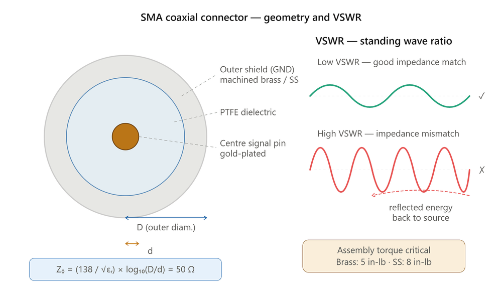
The electrical performance of an SMA connector is governed entirely by transmission line physics and the control of Voltage Standing Wave Ratio (VSWR). An ideal RF channel maintains a perfectly flat 50 Ohm characteristic impedance along its entire path. Any physical variation in the internal diameter of the connector pins, or any gap in the surrounding dielectric material (typically solid PTFE), creates a localized impedance mismatch.
This mismatch causes a portion of the traveling RF wave to bounce backward toward the transmitter, combining with the incoming wave to create standing waves. A high VSWR indicates severe reflection losses, which drastically cut signal transmission range and can generate destructive back-voltage that can overheat and ruin the system's power amplifier.
Tight Mechanical Tolerances
Achieving a low VSWR at high gigahertz frequencies requires tight control over mechanical tolerances during assembly. The characteristic impedance of a coaxial structure is mathematically defined by the ratio of the outer diameter of the inner conductor to the inner diameter of the outer shield, combined with the dielectric constant of the insulating material. If the center pin is slightly bent, off-center, or if the PTFE dielectric insulator is compressed during assembly, the spatial ratio shifts instantly, creating a major electrical discontinuity.
To protect this geometry, high-performance SMA connectors feature gold-plated machined brass or stainless steel shells that maintain rigid structural alignment throughout the component's operational life.
Calibrated Torque Requirements
The mechanical installation process of an SMA connector is heavily tied to its electrical performance. SMA connectors utilize a threaded coupling nut mechanism that requires a specific installation force. Hand-tightening an SMA connector is highly discouraged in professional RF engineering:
- Under-tightening: An air gap forms between the internal mating reference planes, causing a massive inductive impedance spike.
- Over-tightening: Distorts the delicate gold-plated internal mating surfaces, causing permanent physical deformation and ruining the component's high-frequency tuning.
- Correct practice: RF technicians utilize calibrated break-over torque wrenches set to an exact specification—typically 5 inch-pounds for brass variants or 8 inch-pounds for stainless steel shells.
Precision as a Performance Requirement
SMA and RF coaxial interconnects serve as the primary gateways for high-frequency wireless and analog signal distribution. Successfully deploying these microwave-grade pipelines requires selecting high-conductivity machined alloys to minimize skin effect losses, managing internal pin-to-shield spatial dimensions to hold a flat 50 Ohm impedance profile, and enforcing strict calibrated assembly torque limits. When these precise mechanical and electrical boundaries are carefully maintained, RF channels deliver flawless signal purity across high-performance communication systems.