Changing the Axis of Routing
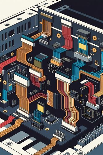
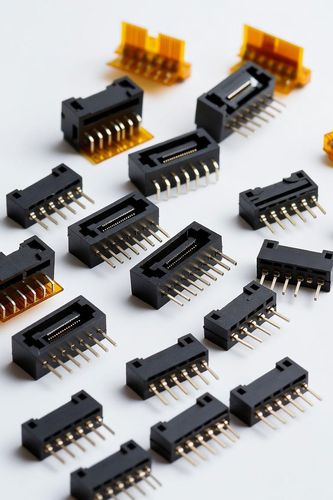
While parallel mezzanine configurations dominate standard stacked architectures, many electronic systems require routing across entirely different geometric planes. When a daughtercard must sit completely perpendicular (90 degrees) to a main motherboard—such as standard PCIe expansion slots or backplane architectures—or when two PCBs must sit side-by-side on the exact same flat horizontal plane, engineers deploy right-angle board-to-board connectors.
By introducing a precise 90 degree bend within the internal pin matrix, right-angle connectors enable co-planar and perpendicular modular configurations. This layout choice introduces distinct physical and electrical considerations, requiring careful management of physical trace length differences, mechanical lever arms, and structural reinforcement.
Structural Typologies — Perpendicular vs. Co-Planar
Perpendicular (90 Degree) Architectures
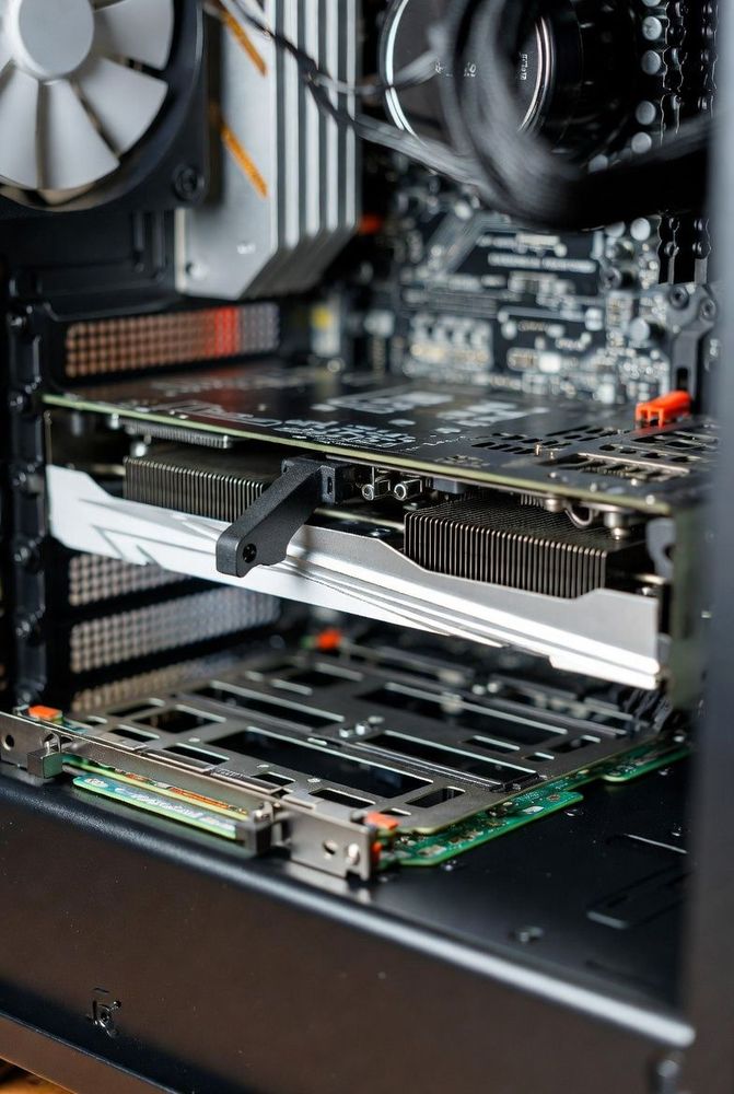
In a perpendicular configuration, a vertical daughtercard plugs directly into a right-angle connector mounted to a horizontal motherboard. This is the bedrock layout for server blades, modular industrial power racks, and gaming motherboards. It optimizes thermal airflow by allowing tall daughtercards to line up cleanly with forced-air cooling paths.
Co-Planar (Side-by-Side) Interfaces
Co-planar layouts occur when two right-angle connectors mate face-to-face, extending two PCBs horizontally on the exact same plane. This layout is common in LED lighting bars, linear sensor strips, and ultra-slim consumer AV products where vertical space is tightly constrained.
The Electrical Challenge — Managing Contact Skew
The defining electrical characteristic of a right-angle connector is its asymmetric internal pin length. Because the pins must form a 90 degree bend, the outermost pins (the outer radius of the turn) are physically longer than the innermost pins (the inner radius of the turn).
This difference in physical path length introduces propagation delay skew. Within a high-speed differential pair, the signal traveling along the longer outer pin will arrive slightly later than the signal on the shorter inner pin. This delay shifts the phase relationship of the differential signals, converting a portion of the differential mode energy into common-mode noise, which degrades signal integrity and generates EMI.
To combat this, high-speed right-angle connectors utilize internal geometric compensations, or require layout engineers to manually add length-matching delay bends directly into the PCB traces right before they enter the connector pads.
Mechanical Lever Arms and Structural Reinforcement
Right-angle configurations are subject to severe mechanical loading. When a technician pushes downward on a tall, perpendicular daughtercard, the card acts as a lever arm, multiplying the force transmitted directly to the connector's solder joint pads on the motherboard.
Without robust physical reinforcements, this leverage can effortlessly tear the SMT signal pads right off the fiberglass PCB substrate. To stop this mechanical failure mode:
- Integrated Hold-Downs: High-quality right-angle connectors incorporate heavy, through-hole metal pegs or rugged side tabs that are soldered directly into the PCB's internal grounding layers, absorbing the mechanical mating and unmating forces.
- Guide Modules and Card Cages: For large-scale perpendicular boards, the connector should never be the sole mechanical anchor. Structural card guides or rigid outer sheet-metal frames are integrated to support the weight of the card, ensuring the right-angle connector bears nothing but clean, linear insertion forces.
Overcoming Axis Constraints
Right-angle board-to-board connectors break the limits of flat, two-dimensional component layout. Whether configuring a perpendicular server rack to improve airflow or running a co-planar array in a slim consumer module, managing these interfaces requires a balanced design approach. By neutralizing internal pin skew, configuring proper mechanical support to absorb lever-arm stresses, and matching structural hold-downs to expected handling forces, engineers create versatile, multi-axis system configurations that stand up to long-term field use.