The Orientation Problem
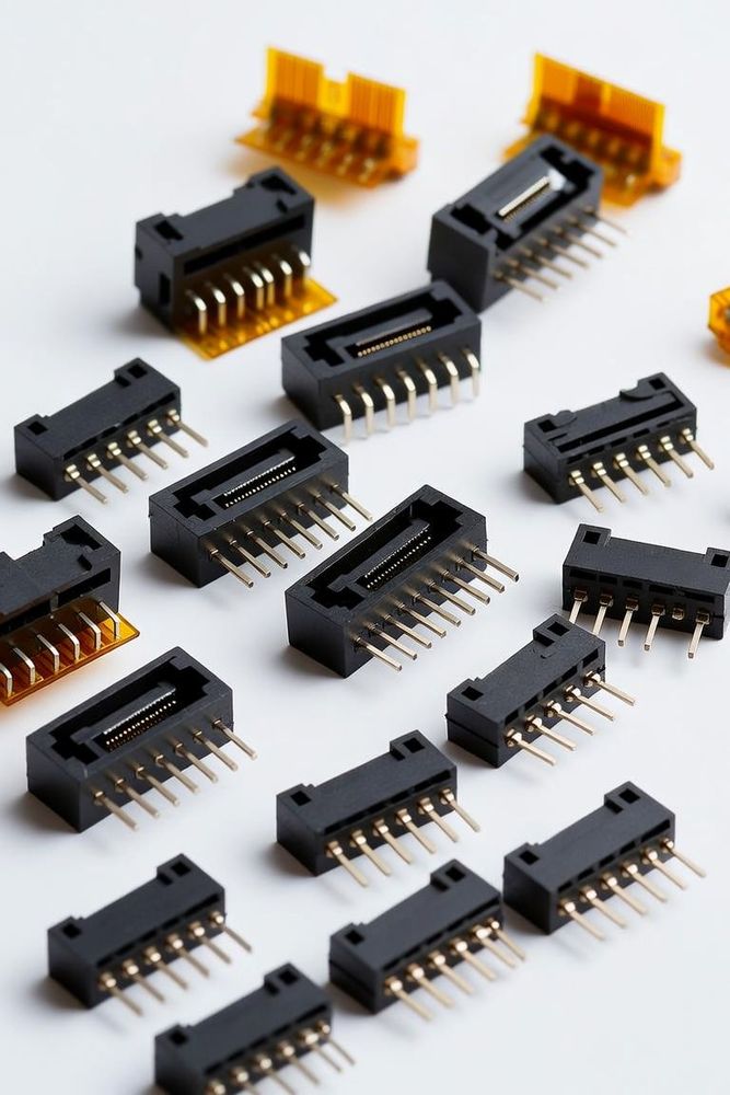
Selecting an FFC/FPC connector involves more than just choosing pin counts and locking styles; engineers must also determine the precise physical location of the internal contact points. Standard flexible flat cables are single-sided, meaning their conductive copper traces are exposed on only one face of the substrate, while the opposite side is covered by a protective insulating polyimide overlay. To accommodate this, FPC connectors are manufactured in three distinct layout configurations: top-contact, bottom-contact, and dual-contact. Misaligning the orientation of the cable traces with the contact layout is a common design oversight that results in a completely dead circuit.
Bottom-Contact Configuration
In a bottom-contact configuration, the spring-loaded metal terminals are positioned along the floor of the connector housing, facing upward. This setup requires the flexible cable to be inserted with its exposed copper traces facing down toward the PCB substrate. Bottom-contact models are the industry workhorses; because the terminals sit flush against the bottom housing wall, they offer exceptional structural stability and are highly compatible with standard SMT reflow soldering processes. They are ideal when the flexible cable naturally drops down from an upper component straight onto the board surface.
Top-Contact Configuration
A top-contact configuration positions the terminal springs along the upper roof of the connector cavity, pressing downward. In this layout, the flexible cable must be inserted with its exposed metal traces facing upward, away from the PCB. Top-contact connectors are crucial when a flexible circuit must fold over on itself in a tight loop, reversing its trace orientation, or when routing signals from a component located directly above the connector assembly. Using a top-contact layout in these scenarios prevents engineers from having to add complex twist patterns to the flexible cable, which could induce stress fractures in the thin copper lines.
Dual-Contact Configuration
To completely eliminate orientation errors on the manufacturing floor, engineers frequently turn to dual-contact configurations. These high-performance connectors integrate independent spring contacts on both the roof and the floor of the internal cavity. Because the connector features symmetrical mating points on both sides, it can accept the flexible cable regardless of whether the exposed traces are facing up or down.
Beyond preventing assembly errors, dual-contact housings allow a single PCB footprint to interface with multiple revisions of a flexible harness, streamlining supply chain logistics and reducing the overall component bill of materials (BOM).
Configuration Summary
- Bottom-Contact: Terminal on housing floor facing up; cable traces face down. Best for standard low-profile routing and maximum solder stability.
- Top-Contact: Terminal on housing roof facing down; cable traces face up. Best for folded/looped cable layouts and high-clearance tracking.
- Dual-Contact: Terminals on both floor and roof; accepts cable traces up or down. Best for error-proofing high-volume assembly lines and BOM consolidation.
Orientation Determines Continuity
By analyzing the natural path of the incoming cable and choosing between top, bottom, or dual-contact housings, hardware designers can eliminate trace inversion errors, minimize cable bending stresses, and optimize the overall electrical layout of the sub-system.