Thermal Vulnerability in Micro-Pitch SMT Connectors
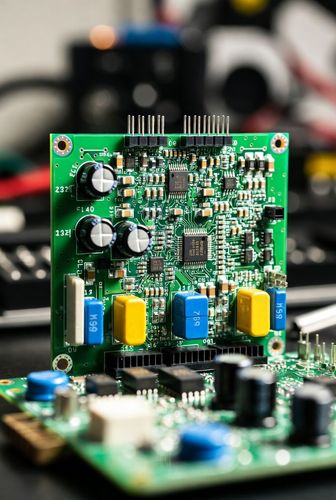
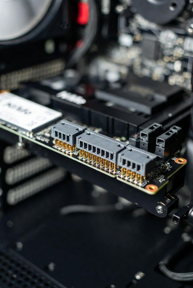
As surface-mount technology (SMT) advances, board-to-board and FPC connectors continue to shrink, pushing pin pitches down to 0.5 mm, 0.4 mm, and 0.3 mm. While high pin density enables sleeker product designs, processing these fine-pitch connectors introduces severe thermal and manufacturing challenges on assembly lines.
The primary difficulty lies in the physical properties of the connector housing. Most micro FPC housings are molded from Liquid Crystal Polymer (LCP) or high-temperature nylon (PA9T). While these thermoplastics withstand standard lead-free reflow profiles (peaking around 240°C to 260°C), they have minimal thermal mass. During manual soldering or hot-air rework, direct heat applied slightly too long will instantly warp or melt the delicate plastic contact dividers, ruining the connector.
Stencil Design and Solder Paste Volume Control
Achieving bridge-free SMT solder joints on fine-pitch connectors begins with precise stencil aperture design during the PCB layout stage. Standard 1:1 stencil apertures often deposit excess solder paste, leading to solder bridging between adjacent pins separated by less than 0.2 mm clearance.
To prevent bridging while ensuring strong mechanical solder joints, engineers should apply aperture reduction rules:
- Aperture Width Reduction: Reduce stencil aperture widths by 10% to 15% relative to the copper pad width, maintaining an aspect ratio greater than 1.5 for clean paste release.
- Staggered Aperture Patterns: For 0.3 mm pitch connectors, use rounded rectangular or "home-steeped" aperture shapes to concentrate paste over the center of the PCB pad rather than the edges.
- Laser-Cut Electropolished Stencils: Utilize nickel-coated or electropolished stainless steel stencils with a thickness of 0.08 mm to 0.10 mm to guarantee consistent paste release volumes.
Professional Drag Soldering and Rework Procedures
When repairing or hand-soldering fine-pitch FPC connectors on prototype boards, standard point-to-point iron techniques are ineffective and risk damaging adjacent pins. Instead, technicians use drag soldering techniques with specialized equipment:
- Inspection and Fluxing: Place the PCB under a stereo inspection microscope and apply a generous layer of high-tack, no-clean synthetic rosin flux along the entire pin array.
- Iron Setup: Equip a temperature-controlled soldering station with a specialized bevel (hoof) or mini-wave tip set to 320°C to 340°C.
- Drag Execution: Load a small pool of molten solder into the cavity of the hoof tip. Touch the tip to the leading edge of the connector pins and glide the iron smoothly along the row at a steady speed. The combination of surface tension and flux draws solder onto the copper pads while leaving spaces between pins clean.
Hot-Air Rework with Bottom-Side Preheating
Replacing a damaged multi-pin micro connector without melting surrounding components requires controlled bottom-side preheating. Applying hot air exclusively from the top creates extreme thermal gradients across the PCB substrate, warping thin boards and scorching the connector plastic long before the hidden pin joints reach reflow temperature.
By placing the PCB on an infrared or conductive bottom preheater set between 150°C and 170°C, the board temperature rises uniformly. Once preheated, applying a low-airflow hot-air nozzle from above at 280°C swiftly reflows the solder joints within 10 to 15 seconds. This short heating window preserves the plastic connector housing while creating clean solder fillets across every pad.