Architectural Decisions in System Hardware Stacking
When engineering multi-board electronics—such as system-on-modules (SoM) connected to carrier boards, server blade expansion cards, or compact consumer handhelds—selecting the optimal inter-board connection strategy is critical. Hardware engineers primarily choose between two architectural approaches: direct precision mezzanine Board-to-Board (B2B) connectors or flexible Cable-to-Board (C2B) assemblies utilizing FPC or ribbon cables.
Both methods offer distinct advantages depending on mechanical enclosures, thermal management constraints, high-frequency signal requirements, and assembly line complexities. Making the correct choice early in the hardware layout phase prevents costly PCB spins and mechanical redesigns late in development cycles.
Mezzanine Board-to-Board Connectors: Density and Performance
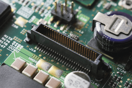
Mezzanine B2B connectors join two parallel PCBs directly without intervening cables. Available in stacking heights ranging from less than 0.6 mm up to 20 mm, these connectors provide ultra-compact physical profiles and exceptionally high contact pin densities, often exceeding 300 pins per square inch.
From a signal integrity perspective, direct mezzanine connections present minimal trace lengths, short insertion paths, and tightly controlled impedance discontinuities. High-speed mezzanine connectors support speeds exceeding 28 Gbps to 56 Gbps per differential pair, making them ideal for high-bandwidth interfaces like PCIe, NVMe, and PAM4 Ethernet channels. Furthermore, direct board stacking simplifies robotic automated surface-mount assembly (SMT) pick-and-place processing, eliminating manual cable routing steps during final device assembly.
The Hidden Challenges of Mezzanine Stacking
Despite their electromechanical benefits, direct mezzanine B2B setups impose rigid mechanical alignment constraints. Rigidly coupling two parallel boards requires tight mechanical tolerances across board standoffs, housing dimensions, and solder pad coplanarity. If tolerances stack up incorrectly, the mechanical stress placed across mated connector shells can fracture solder joints, leading to intermittent open circuits or micro-cracks under thermal cycling.
Additionally, mezzanine stacking creates thermal trapping zones. When a high-power processor on a carrier board sits directly beneath a SOM module with a 3 mm stack height, airflow becomes restricted, complicating heat sink placement and active thermal dissipation. In dense enclosures, vertical stacking heights may also exceed available enclosure thickness.
Cable-to-Board (C2B) Solutions: Flexibility and Separation
Cable-to-Board configurations—utilizing micro-coaxial assemblies, discrete wire harnesses, or flexible printed circuits (FPC)—decouple mechanical and spatial dependencies between PCBs. Boards no longer need to reside in parallel planes; they can sit coplanar, at right angles, or mounted on opposing sides of an internal enclosure wall.
This mechanical flexibility isolates sensitive analog circuits from noisy power supply boards, improves thermal airflow around hot processing units, and eliminates tolerance stack-up stresses. Cable-to-board setups absorb shock, vibration, and chassis flex far more effectively than rigid board stackups, making them standard choices in aerospace, defense, and ruggedized automotive hardware.
System Trade-Off Evaluation
To choose between mezzanine B2B and cable-to-board interconnects, engineers should evaluate their design requirements against three core structural trade-offs:
- Electrical Speed vs. Physical Distance: Mezzanine connectors deliver shorter electrical paths for ultra-high frequencies, whereas cable assemblies allow spatial separation across larger mechanical distances.
- Robotic SMT vs. Manual Assembly: Board-to-board connectors reduce labor costs through pure surface-mount assembly, while cable interconnects often require secondary manual plug-in operations during box builds.
- Thermal Dissipation Envelopes: Decoupling boards with a flexible cable allows dedicated heat sinks and airflow channels around processing components, avoiding thermal saturation between tightly stacked PCBs.
Neither connector methodology is universally superior. Balancing signal integrity targets against mechanical enclosure tolerances, thermal envelopes, and manufacturing complexity dictates the ideal interconnect topology for any given hardware product.