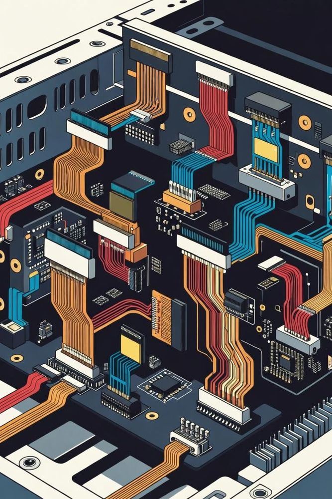
Interface Integrity in Prototyping
Developing custom electronic hardware prototypes has become more accessible thanks to affordable PCB fabrication, accessible EDA software, and open-source desktop fabrication tools. However, bridging the gap between a simulated circuit layout and a working physical prototype remains a challenge. One of the most common points of failure in custom builds occurs at the physical interfaces: the connectors and cabling used to route signals between different circuit boards.
When prototyping custom devices that handle fast signals-such as high-speed SPI busses, high-resolution display interfaces, or differential sensor lines-designers often run into significant signal integrity and mechanical reliability issues. These problems usually stem from using cheap flexible flat cables incorrectly or attempting to hand-assemble micro-connectors with pitches below 2mm without the necessary factory-grade tooling. Understanding these assembly pitfalls is essential for building prototypes that work reliably on the first spin.
The Illusion of Simplicity: Flexible Flat Cables
Flexible Flat Cables and their associated surface-mount receptacles are incredibly popular in modern product development. They offer a thin profile, excellent flexibility, and a simple mechanism for connecting dense rows of parallel lines without using bulky wire harnesses. However, deploying a standard FFC without careful attention to signal routing can quickly ruin high-speed data channels.
A standard off-the-shelf FFC consists of flat copper conductors laminated parallel to one another between thin layers of insulating plastic. Because these lines sit right next to each other over long distances with minimal separation, their mutual capacitance and inductance are high. If a designer routes multiple high-speed data lines adjacent to one another on an FFC without any isolation, the resulting cross-talk will degrade the signals, corrupting data packets and causing intermittent system resets.
To use FFCs safely for high-frequency signals, developers must implement a strict interleaved grounding layout. This approach places a dedicated ground line between every single active signal line on the cable. The ground lines act as physical shields, absorbing electromagnetic energy and giving the returning current a clear path back to the source. This isolation significantly lowers cross-talk and helps keep the cable's characteristic impedance stable.
The Nightmare of Hand-Crimping Sub-2mm Connectors
When a project demands rugged wire-to-board connections, designers frequently select high-density micro-connector families like Molex Micro-Fit, JST PH, or Hirose DF series. These connector lines feature tight contact pitches below 2mm, allowing them to pack significant connectivity into a small footprint. However, assembling the wire harnesses for these connectors by hand is incredibly difficult.
A reliable crimp connection requires a highly precise mechanical deformation. When a wire is pressed into a metal terminal contact, the crimping tool must apply enough localized pressure to deform the copper strands and the terminal barrel together, creating a gas-tight cold weld. This seal keeps out oxygen and moisture, preventing corrosion and maintaining a stable, low-resistance electrical connection over the life of the product.
Attempting to achieve this precise deformation using cheap, generic hand-crimping tools or needle-nose pliers is a recipe for failure. Generic tools rarely apply pressure uniformly across the terminal's insulation and conductor wings. This often leads to over-crimping, which shears the delicate copper strands and weakens the wire, or under-crimping, which leaves air gaps inside the barrel. These loose connections are prone to pulling out under light mechanical stress or developing intermittent open circuits that are incredibly frustrating to track down during debugging.
Production Techniques for Reliable Prototyping
To avoid these common connection issues and keep prototype development moving forward smoothly, designers should adopt several practical assembly strategies. Instead of buying loose contacts and attempting to crimp them by hand, developers can purchase factory-terminated wire leads directly from major component distributors, crimped on calibrated, automated factory tooling. For environments prone to intense electrical noise, designers should bypass standard flat cables in favor of shielded FFC options, which feature a conductive outer foil layer that connects directly to the system ground. If a project requires in-house harness assembly, developers must budget for the manufacturer's official, calibrated hand tools, which feature precise ratcheting mechanisms and custom dies shaped exactly for the target terminal contact, guaranteeing reliable, gas-tight connections on every single build. The same mating-force and contact-reliability principles that trip up hobbyist assemblies scale up directly into production hardware. Our floating connector design guide covers how these fundamentals are managed at an engineering level.