The Geometry of Parallel Processing
In dense electronic architectures, such as blade servers, telecom switches, and advanced industrial control blocks, spatial optimization is a core design constraint. When system requirements dictate expanding circuit real estate without increasing the overall footprint of the primary motherboard, engineers turn to a vertical stacking topology. The connectors that bridge these parallel, overlapping printed circuit boards are known as mezzanine connectors.
Named after the architectural intermediate floor, mezzanine connectors establish short, direct electrical paths between a host motherboard and a daughtercard or module. For the interconnect engineer, specifying a mezzanine system involves navigating complex mechanical tolerances, high pin counts, thermal airflow restrictions, and strict signal integrity boundaries over micro-scale distances.
Mechanical Metrics and Stack Height Optimization
The defining metric of a mezzanine interconnect system is its stack height—the absolute distance between the top surface of the motherboard and the bottom surface of the mezzanine daughtercard when fully mated.
Coplanarity and Pin Counts
Modern mezzanine systems are heavily biased toward surface-mount technology (SMT) to maximize routing space on the opposite sides of the PCBs. However, as pin counts scale from 40 to over 500 positions in high-density arrays, coplanarity becomes a critical manufacturing threshold. Coplanarity defines the maximum distance between the lowest and highest contact solder tail before surface mounting.
For fine-pitch mezzanine arrays, coplanarity must be strictly maintained within 0.10 mm (0.004 inches). If a single pin drifts outside this tolerance during reflow, it will create an open circuit or a structurally weak solder joint, jeopardizing the mechanical integrity of the entire parallel board stack.
Stacking Tolerances and Alignment
Mating two rigid, parallel boards over a multi-pin array leaves no room for angular or axial misalignment. Unlike flexible wire-to-board harnesses, a mezzanine interface locks both boards into a rigid spatial relationship. To prevent localized stress on solder joints, high-performance mezzanine connectors incorporate molded alignment posts or heavy polarization shrouds that capture the daughtercard and force absolute alignment before the internal male and female contacts meet.
Structural Configurations — Hermaphroditic vs. Two-Piece Systems
Two-Piece Header and Receptacle Systems
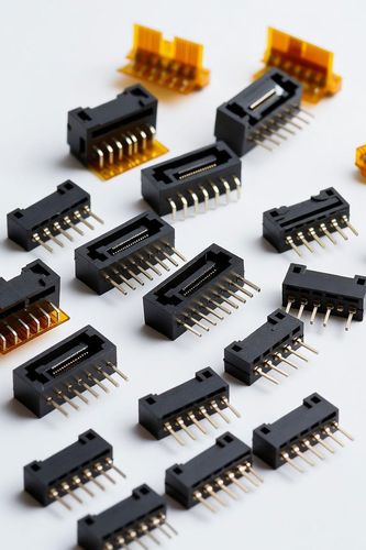
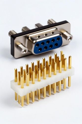
The traditional approach utilizes a distinct male header mated to a corresponding female receptacle. The stack height is varied by the manufacturer offering different profile options for either the plug, the socket, or both. This allows engineers to scale their stack heights (typically from 2.0 mm up to 30 mm) to clear tall on-board components like capacitors, inductors, or low-profile heatsinks on the motherboard, using the exact same PCB layout footprint.
Hermaphroditic (Self-Mating) Connectors
An elegant alternative is the hermaphroditic connector, where the interface profile is identical on both sides. Any connector can mate with any other connector of the same series. This drastically simplifies bill of materials (BOM) management, cuts qualification costs in half, and streamlines high-volume SMT inventory management, though it typically restricts the system to a single, fixed stack height.
Thermal and Airflow Dynamics
Stacking boards directly on top of one another creates an inherent thermal trap. In high-power modules, such as AI accelerator blocks or embedded military computing racks, components generating heavy thermal loads are squeezed into the narrow gap between the parallel PCBs.
Mezzanine connectors must be strategically oriented and selected to minimize blockages to the system's forced-air cooling paths:
- Open-Pin Field Arrays: Utilizing wide grid matrices rather than solid plastic walls allows air to circulate through the connector body itself.
- Stack Height Clearance: Increasing the stack height from a tight 4 mm to a wider 10 mm can drop the thermal resistance of the air gap, allowing high-velocity cooling air to sweep across hot components, preventing localized thermal throttling.
Scalability and Integration
Mezzanine connectors transform a static, two-dimensional PCB layout into a modular, three-dimensional computing ecosystem. By selecting the correct blend of stack height, managing tight SMT coplanarity limits, and balancing the mechanical simplicity of hermaphroditic systems against the variable height profiles of traditional two-piece headers, engineers create scalable, rugged parallel architectures capable of handling next-generation processing densities.